Wheelock Exceder LED3 speaker ceiling install sheet P85445

File Preview
Click below to download for free
Click below to download for free
File Data
| Name | wheelock-exceder-led3-speaker-ceiling-install-sheet-p85445-3459120867.pdf |
|---|---|
| Type | |
| Size | 1.34 MB |
| Downloads |
Text Preview
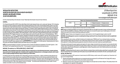
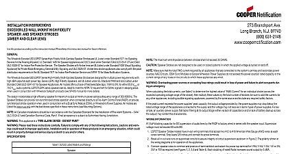
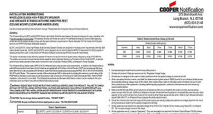
SPECIFICATIONS screw terminal Strip leads 3 8 inches and connect to screw terminals INSTRUCTIONS LED CEILING MOUNT HIGH FIDELITY AND SPEAKER STROBES AND AMBER LENS this product according to this instruction manual Please keep this instruction manual for future reference Wheelock Exceder LED LSPSTxC Series High Fidelity Multi Candela Speaker Strobes are UL Listed under Standard 1971 for Signaling for the Hearing Impaired UL Standard 1480 for Speaker Appliances and ULC Listed under Standard CAN ULC S541 07 and CAN for indoor Fire Protective Service The Speaker Strobes with Amber lens are UL Listed under Standard 1638 Visual Signal Appliance for Private Mode Emergency General Utility Signaling UL Standard 1480 for Speaker Appliances and ULC S526 07Amber strobe appliances also comply with the polar distribution requirements in the UL Standard 1971 for Indoor Fire Protection Service and for Mass Notification Systems They are designed for multiple power requirements with high dBA output at each power tap and are for ceiling mounting only Series LSPKxC High Fidelity Speakers are UL Listed under UL Standard 1480 and ULC Listed under CAN ULC S541 07 for Speaker Appliances and can be ceiling or wall mounted All models offer a choice of field selectable taps to 2W for either 25.0 VRMS or 70.0 VRMS audio systems The design incorporates a high efficiency speaker for maximum output at mini power across a frequency range of 300 8000Hz The Speaker Strobes can provide non synchronized strobe operation when connected to a Fire Alarm Control Panel FACP or provide synchronized strobe operation when used in conjunction with a Dual Sync Module or Wheelock Power Supplies All models are Listed for indoor use only with the backboxes specified in these instructions see Mount Options LSPSTC LSPKC series speakers are UL rated to meet the NFPA 72 requirement for 520Hz signals in sleeping areas when in conjunction with Wheelock Safepath products see SP40S manual for more details All Canadian Installations should be in accordance with the Canadian Standard for the Installation of Fire Alarm Systems CAN and Canadian Electrical Code Part 1 Final acceptance is subject to Authorities Having Jurisdiction This appliance is a ALARM DEVICE DO NOT PAINT Please read these instructions carefully Failure to comply with any of the following instructions cautions and warn could result in improper application installation and or operation of these products in an emergency situation which could in property damage and serious injury or death to you and or others 1 UL ULC Listed Models and Ratings at 10 Feet Rated Watts Per UL 1480 dBA CAN ULC S541 07 when ordering denotes the product color W White R Red LSPSTxC A for amber lens Strobes will produce 1 flash per second over the Voltage range All models are Listed for indoor use with a temperature range of 32 to 120 0 to 49 and maximum humidity of 93 RH effect of shipping and storage temperatures shall not adversely affect the performance of the appliance when it is stored in the cartons and is not subjected to misuse or abuse dBA is rated per UL Standard 1480 and ULC Standard ULC S541 07 for Speaker Appliances Frequency range of speakers is 300 These appliances were tested to the operating voltage limits of 16 33 volts using Filtered DC or unfiltered Full Wave Rectified FWR not apply 80 and 110 of these voltage values for system operation Check the minimum and maximum output of the power supply and standby battery and subtract the voltage drop from the circuit resistance to determine the applied voltage to the strobe 2 Current Ratings for Strobe Only RMS Current AMPS Range Voltage LSPSTxC LSPSTxC A NOTE Candela setting will determine the current draw of the product Make sure that the total RMS current required by all appliances that are connected to the system primary and secondary power NAC Circuits DSM Sync Modules or Wheelock Power Supplies do not exceed the power sources rated capacity or the current of any fuses on the circuits to which these appliances are wired Speaker Strobes are not designed to be used on coded systems in which the applied voltage is cycled on and off Overloading power sources or exceeding fuse ratings could result in loss of power and failure to alert occupants dur an emergency calculating the total currents use Table 2 to determine the highest value of Current for an individual strobe across the operating voltage range of the strobe then multiply these values by the total number of strobes be sure to add the currents for other appliances including audible signaling appliances powered by the same source and include any required safety factors the peak current exceeds the power supplies peak capacity the output voltage provided by the power supplies may drop below the voltage range of the appliances connected to the supply and the voltage may not recover in some types of power supplies For ex an auxiliary power supply that lacks filtering at its output stage either via lack of capacitance and or lack of battery backup across output may exhibit this characteristic The following figures show the maximum number of field wires conductors that can enter the backbox used with each mounting option If limits are exceeded there may be insufficient space in the backbox to accommodate the field wires and stresses from the wires could damage the INFORMATION 1.5 blocking capacitor for DC supervision of audio lines by the FACP is factory wired in series with the speaker input Supervision must not exceed 33 VDC Speaker and Speaker Strobe models have in out wiring terminals that accept two 12 to 18 American Wire Gauge AWG wires at Break all in out wire runs on supervised circuits to assure integrity of circuit supervision as shown in Figure 2 The polarity shown in wiring diagrams is for operation of the appliances Connect speaker wires to common and positive of terminal block and select the power tap terminal for 1 8W 1 4W 1 2W 1W or 2W or 70V as required see Figures 1 2 3,5 and Table 4 Each doubling of rated Watts increases sound output by 3 dBA Using the slide switch shown in Figure 3 select voltage and wattage as shown in Table 4 Each letter corresponds to a position of the located on the printed circuit board Refer to Sync Module instruction sheets DSM P83177 or Wheelock Power Supplies for additional information Figure 1 LED Strobe Wiring Figure 2 Wire Connection Check electrical ratings specified in Tables 1 and 2 as appropriate to ensure proper electrical input Ensure the speaker wiring is to speaker terminals only and strobe wiring is connected to strobe terminals only Ensure the wiring at the FACP is correct Wiring method shall be in accordance with CSA C22.1 Canadian Electrical Code Part 1 Safety Standard for Electrical Installa Section 32 Improper electrical input can damage the product or cause it to malfunction The Speaker Strobe appliances must be set to the desired dBA sound output level before they are installed This is done by setting the slide switch in accordance with these instructions Incorrect settings will result in improper performance Factory setting is F 70V 1 2 W 3 ULC Directional Characteristics 75 degrees horizontal 70 degrees vertical 90 degrees horizontal 90 degrees vertical Slide the Switch Indicator selection switch to the desired tap setting Figure 3 Speaker Selection Switch NOTE The maximum wire impedance between strobes shall not exceed 35 OHMS Branchport Ave Long Branch N J 07740 800 631 2148 www coopernotification comPN P85445ECopyright 2015 Cooper Wheelock Inc dba Cooper Notificationfirealarmresources com CAUTION Always operate audio amplifiers and speakers within their specified ratings Excessive input may distort sound quality may damage audio equipment Improper input voltage can damage speaker If distortion is heard check for clipping of the audio with an oscilloscope and reduce the amplifier input level or gain level to eliminate any clipping 4 Speaker Voltage and Wattage Connection Chart