Wheelock MT and MT4 horn install sheet P82467

File Preview
Click below to download for free
Click below to download for free
File Data
| Name | wheelock-mt-and-mt4-horn-install-sheet-p82467-0129637485.pdf |
|---|---|
| Type | |
| Size | 1.31 MB |
| Downloads |
Text Preview
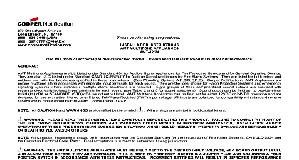
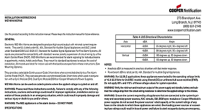
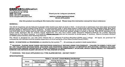
INSTALLATION INSTRUCTIONS APPLIANCES MT 12 24 AND this product according to this instruction manual Please keep this instruction manual for future reference 2 UL ULC Current Ratings for MT Multitone Audible Appliances RMS Current AMPS Multitone Appliances are UL Listed under Standard 464 for Audible Signal Appliances for Fire Protective Service The MT 12 24 is ULC Listed under Standard CAN ULC S525 07 for Audible Signal Appliances for Fire Alarm Systems They are listed for both indoor outdoor use with the backboxes specified in these instructions See Mounting Options MT Multitone Appliances can be field set to any one of eight commonly used alarm tones Sound output can be field set to provide either HIGH HI dBA or STANDARD STD sound output level MT Multitone Appliances can be field set for either 12VDC or 24VDC operation and are designed for use with filtered or unfiltered Full Wave Rectified FWR input voltage All inputs are polarized for compatibility with standard reverse polarity of circuit wiring by a Fire Alarm Panel FACP All Canadian installations should be in accordance with the Canadian Standard for the Installation of Fire Alarm Systems CAN and the Canadian Electrical Code Part 1 Final acceptance is subject to authorities having jurisdiction Please read these instructions carefully before using this product Failure to comply with any of the following instruc cautions and warnings could result in improper application installation and or operation of these products in an emergency which could result in property damage and serious injury or death to you and or others Description Horn Hz Modulated 0.07 ON Repeat Horn 0.25 Sec ON 0.25 OFF Repeat The MT appliance is a FIRE ALARM DEVICE DO NOT PAINT 3 3 ANSI S3.41 Temporal Hz ANSI S3.41 Pattern Sweep 4.0 ON 0.5 Sec OFF Sweep 1.0 ON Repeat Hz 0.25 Sec ON VDC VFWR VDC VFWR Ensure the total RMS current and total average current required by all appliances that are connected to the system and secondary power sources NAC circuits SM DSM sync modules or Cooper Wheelock power supplies do not the power sources rated capacity or the current ratings of any fuses on the circuits to which these appliances are wired power sources or exceeding fuse ratings could result in loss of power and failure to alert occupants during an emer which could result in property damage and serious injury or death to you and or others calculating the total currents Use Table 2 to determine the highest value of RMS Current for an individual MT Multitone then multi these values by the total number of MT Multitones be sure to add the currents for any other appliances powered by the same source include any required safety factors the peak current exceeds the power supplies peak capacity the output voltage provided by the power supplies may drop below the voltage range of the appliances connected to the supply and the voltage may not recover in some types of power supplies For ex an auxiliary power supply that lacks filtering at its output stage either via lack of capacitance and or lack of battery backup across output may exhibit this characteristic 1 UL ULC Listed Models Ratings Ratings Range 10 Feet or or Range or at 10 All models are listed for indoor and outdoor use with a temperature range of 40 to 66 40 to 151 and maximum of 98 2 RH For UL ULC applications these appliances were tested at UL to the operating voltage limits of 16 33VDC for 24VDC and 8 17.5VDC for 12VDC operation using filtered DC or unfiltered full wave rectified FWR Do not apply 80 and of these voltage values for system operation Verify the minimum and maximum output of the power supply and standby battery and subtract the voltage drop from circuit wiring resistance to determine the applied voltage to the strobes Branchport Ave Long Branch N J 07740 800 631 2148 www coopernotification comPN P82467 001SCopyright 2012 Cooper Wheelock Inc dba Cooper Notificationfirealarmresources com 3 dBA Ratings at 10 Feet 5 Input Voltage and dBA Sound Output Level Settings Reverberant Ratings Per UL 464 Anechoic Ratings Per CAN ULC S525 07 Voltage and Decibel Level and SW1 Settings 3 3 24VDC 12VDC 24VDC 12VDC For ULC applications only Code 3 Horn and Code 3 Tone are required to meet the ULC minimum of 85 dBA and the audible signal pattern mandated by the National Building Code of Canada 4 ULC Directional Characteristics 35 degrees left 35 degrees right 55 degrees left 55 degrees right 35 degrees upward 35 degrees downward 55 degrees upward 55 degrees downward Jumper Plug DP1 and Switch SW1 of the MT Multitone Appliance shown in Figure 1 are used to set the desired input voltage dBA sound level and alarm tone The factory settings are shown below Read these instructions carefully before changing any of these factory settings HERE FOR 0 HERE FOR 1 2 3 4 1 PC Board Layout Showing Location of Jumper Plug DP1 and Switch SW1 factory settings are 24VDC DP1 set on 24 HIGH dBA SW1 POS 1 set on HORN TONE SW1 POS 2 3 4 set on 1 1 1 1 Set desired input voltage and dBA sound output level as follows Refer to Figures 2 and 3 Multitone Appliances are field set for input voltage and dBA sound output level by inserting a Jumper Plug DP1 and adjusting a four Switch SW1 as shown in Table 5 and Figures 2 and 3 Use DP1 to select the desired voltage and SW1 Position 1 to select the sound output level OPTIONS VDC HIGH dBA VDC STD dBA VDC HIGH dBA VDC STD dBA SET ON 12 PLUG SET ON 24 DP1 on 24 set SW1 POS 1 on 1 Factory Setting DP1 on 24 set SW1 POS 1 on 0 DP1 on 12 set SW1 POS 1 on 1 DP1 on 12 set SW1 POS 1 on 0 HERE FOR 1 HERE FOR 0 A SMALL SCREWDRIVER TO THE SWITCH POSITION 1 2 3 4 2 Jumper Plug DP1 Settings 3 Switch SW1 Settings Needle Nose Pliers to Lift and Properly Insert the Jumper Plug Do not apply 24VDC input if the jumper plug DP1 is set on 12 This can damage the unit Verify the jumper plug DP1 switch SW1 settings to make sure they are correct Improper settings can damage the unit or result in no sound output or dBA sound output level that is below code requirem