Wheelock MT4-115 multitone horn strobe install sheet P83160

File Preview
Click below to download for free
Click below to download for free
File Data
| Name | wheelock-mt4-115-multitone-horn-strobe-install-sheet-p83160-7205361498.pdf |
|---|---|
| Type | |
| Size | 904.82 KB |
| Downloads |
Text Preview
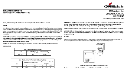
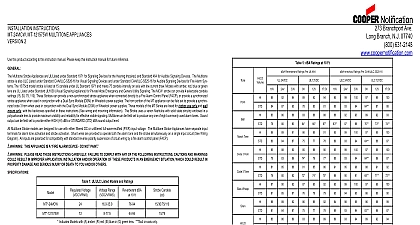
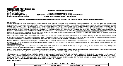
INSTALLATION INSTRUCTIONS MULTITONE STROBE APPLIANCE this product according to this instruction manual Please keep this instruction manual for future reference Multitone Strobe Signals are UL Listed under Standard 464 and 1638 for Private Mode Fire Protective Signaling Service are listed for both indoor and outdoor use with the backboxes specified in these instructions See Mounting Information Multitone Strobe Signals can be field set to produce any one of eight commonly used alarm tones Sound output can be set to provide either HIGH HI dBA or STANDARD STD dBA sound output level They are available with a MT4 115 WH Xenon Tube with an intensity of 15 candela cd MT4 115 WH Multitone Strobe Signals have separate input terminals for alarm tone activation and strobe activation Shunt wires are to operate both the alarm tone and the strobe simultaneously on a single input circuit See Wiring Diagram All inputs have a DC capacitor for compatibility with supervision when used with a Fire Alarm Control Panel F A C P Please read these instructions carefully before using this product The Multitone Strobe Signals must be field set to desired dBA sound output level and alarm tone before they are installed This is done by properly inserting a jumper plug and a four position switch in accordance with these instructions Incorrect settings will result in improper performance and damage the product and could result in property damage and serious injury or death to you and or others Not recommended for use at refrigerator freezer door entrances or other areas with persistent condensations 1 UL Listed Models and Ratings for Multitone Appliances VRMS VRMS Current Per 1638 NOTES are designed to flash at approximately 1 flash per second with continuous nominal applied voltage Do not use strobes coded or interrupted circuits is UL Listed for indoor outdor use with a temperature range of 31 to 150 35 to 66 and maximum of 95 RH For UL applications these appliances were tested to the operating voltage limits of 96 132 volts Do not apply 80 110 of these voltage values for system operation 2 Candela at Various Angles at Various AnglesPer UL 1638 3 dBA and Current Ratings for Multitone Audible Only Time Horn Horn Tone Whoop RMS Current dBA 10 Feet Per UL 464 If the strobe and audible are wired to operate in unison on a single circuit add strobe current from Table 1 to audible signal current Table 3 to obtain total current for each unit If Multitone Strobe signals are operated within 15 inches of a person ear they can produce a sound pressure level exceeds the maximum 120 dBA permitted by ADA and OSHA rules Exposure to such sound levels can result in damage to a hearing Ensure the total RMS current required by all appliances that are connected to the system primary and secondary sources do not exceed the power sources rated capacity or the current ratings of any fuses on the circuits to which these are wired Overloading power sources or exceeding fuse ratings could result in loss of power and failure to alert oc during an emergency which could result in property damage and serious injury or death to you and or others calculating the total currents Use Table 1 and 3 to determine the highest value of RMS Current for an individual strobe across the operating voltage range of the strobe then multiply these values by the total number of strobes be sure to add the currents for other appliances including audible signaling appliances powered by the same source and include any required safety factors Ensure all fuses used on signaling circuits are rated to handle the maximum inrush or peak current from all devices on circuits Failure to do this may result in loss of power to the signaling circuit and the failure of all devices on that circuit to which could result in property damage and serious injury or death to you and or others Multitone audible signals produce a brief inrush current that lasts for just 50 microseconds but can reach a peak value of 5.0 Amps Switch SW1 of the Multitone Signal shown in Figure 1 is used to set the desired dBA sound output level and alarm tone The factory are shown below Read these instructions carefully before changing any of these factory settings HERE FOR 0 HERE FOR 1 2 3 4 AUD 1 PC Board Layout Showing Location of the Switch SW1 HERE FOR 1 HERE FOR 0 A SMALL SCREWDRIVER TO THE SWITCH POSITION 1 2 3 4 2 Switch SWI Settings Branchport Ave Long Branch N J 07740 800 631 2148 www coopernotification comPN P83160FCopyright 2012 Cooper Wheelock Inc dba Cooper Notificationfirealarmresources com factory settings are HIGH dBA SW1 POS 1 set on 1 HORN TONE SW1 POS 2 3 4 set on 1 1 1 NOTES 1 The 115VAC Multitone Strobe signals cannot be field set for input voltage desired dBA sound output level as follows refer to Figure 2 and Table 4 4 dBA Sound Output Level Settings Level dBA dBA dBA Switch Settings POS 1 Factory Setting 2 Set desired alarm tone as follows refer to Figure 2 and Table 5 Multitone Signals are field set for any one of eight alarm tones by setting a four position switch SW1 as shown in Figure 2 Table 5 Use SW1 POS 2 3 4 to select the desired alarm tone refer to Table below Time Horn Horn Tone Whoop 5 Alarm Tones Description Switch Settings 2 3 4 OPTIONS Horn Continuous Factory Setting Hz Modulated 0.07 Sec ON Repeat 0.25 Sec ON 0.25 Sec OFF Repeat ANSI S3.41 Temporal Pattern Hz ANSI S3.41 Temporal Pattern Hz Sweep 4.0 Sec ON 0.5 Sec OFF Repeat Hz Sweep 1.0 Sec ON Repeat Hz 0.25 Sec ON Alternate If sheathed multiconductor cable or 3 4 inch conduit fittings are used verify the installed product has sufficient clearance and room prior to installing backboxes and conduit weather resistant installation use outdoor mounting option Outdoor backbox must be mounted vertically with as to allow any moisture or condensation to drain properly through drain holes on bottom of backbox MT4 115 WH can be surface mounted to a standard 4 inch square by 2 1 8 inch deep electrical box Figure A weather resistant WBB Figure B or a 4 inch square by 1 1 2 inch extension ring and a 4 inch square by 2 1 8 inch deep electrical box Figure C largest backbox shown in Mounting Options where possible to provide additional wiring room for easy installation entrance to backboxes should be selected to ensure sufficient wiring clearance for installed equipment When extension rings required conduit should enter through backbox not extension ring Use Steel City 53151 1 1 2 inches deep or 53171 2 1 8 inches extension rings or equal with same area cut out in back care and proper techniques to position the field wires in the backbox so they use minimum space and produce minimum stress on the This is especially important for stiff heavy gauge wires with thick insulation or sheathing not pass additional wires used for other than signaling devices through the backbox Such additional wires could result in insufficient space for the signaling device Code 3 Horn and Code 3 Tone incorporate the temporal pattern specified by ANSI NFPA ISO for standard emergency evacuation They should be used only for fire evacuation signaling and not for any other purpose Horn and Bell Tones can be used on coded systems with a minimum On Time of 1 4 of a second All other tones are recommended use only on continuous non coded systems The following figures show the maximum number of field wires conductors that can enter the backbox used with each mount option If these limits are exceeded there may be insufficient space in the backbox to accommodate the field wires and stresses from wires could damage the product the limits shown for each mo