Wheelock MTWP colored lens horn strobe install sheet P84601

File Preview
Click below to download for free
Click below to download for free
File Data
| Name | wheelock-mtwp-colored-lens-horn-strobe-install-sheet-p84601-8013296574.pdf |
|---|---|
| Type | |
| Size | 763.26 KB |
| Downloads |
Text Preview
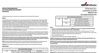
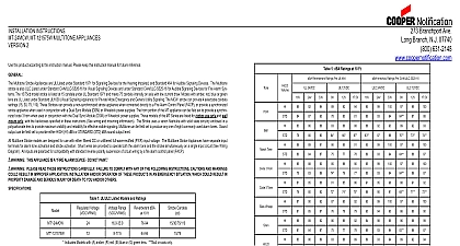
Branchport Avenue Branch NJ 07740 631 2148 USA 397 5777 CANADA Thank you for using our products MULTITONE STROBE COLOR LENS APPLIANCES INSTALLATION INSTRUCTIONS this product according to this instruction manual Please keep this instruction manual for future reference Multitone Strobe Appliances can provide a non synchronized strobe appliance when connected directly to a Fire Alarm Control Panel FACP or a synchronized strobe appliance when used in conjunction with a Sync Module SM Dual Sync Module DSM or Wheelock Power Supplies Multitone Strobe Appliances use a Xenon flashtube with solid state circuitry enclosed in a rugged Lexan lens to provide maximum visibility and for effective visible signaling is a registered trademark of General Electric Company Strobe Appliances can be field set to produce any one of eight commonly used alarm tones Sound output can be field set to provide either HI dBA or STANDARD STD dBA sound output level Multitone Strobe models are designed for use with either filtered DC or unfiltered Full Wave Rectified FWR input voltage The Multitone Strobe have separate input terminals for alarm tone activation and strobe activation Shunt wires are provided to operate both the alarm tone and the simultaneously on a single input circuit See Wiring Diagram All inputs are polarized for compatibility with standard reverse polarity of circuit wiring by a Fire Alarm Control Panel FACP All CAUTIONS and WARNINGS are identified by the symbol All warnings are printed in bold capital letters PLEASE READ THESE INSTRUCTIONS CAREFULLY BEFORE USING THIS PRODUCT FAILURE TO COMPLY ANY OF THE FOLLOWING INSTRUCTIONS CAUTIONS AND WARNINGS COULD RESULT IN IMPROPER APPLICATION AND OR OPERATION OF THESE PRODUCTS IN AN EMERGENCY SITUATION WHICH COULD RESULT IN DAMAGE AND SERIOUS INJURY OR DEATH TO YOU AND OR OTHERS 1 Models and Ratings Voltage Candela Axis C C 10 Feet lens will produce 1 flash per second over the Voltage Range MT models are for indoor use with a temperature range of 32 to 120 0 to 49 and maximum humidity of 93 2 RH Candela ratings in Table 1 are for clear lens Derate approximately 25 for amber lens 55 for green lens 70 for blue lens and 80 for THE MAXIMUM WIRE IMPEDENCE BETWEEN STROBES SHALL NOT EXCEED 35 OHMS THE MAXIMUM NUMBER OF ON A SINGLE NOTIFICATION APPLIANCE CIRCUIT SHALL NOT EXCEED 47 THE MULTITONE STROBE APPLIANCES MUST BE FIELD SET TO THE DESIRED dBA SOUND OUTPUT LEVEL ALARM TONE BEFORE THEY ARE INSTALLED THIS IS DONE BY PROPERLY INSERTING A JUMPER PLUG AND A FOUR POSITION SWITCH IN ACCORDANCE WITH THESE INSTRUCTIONS INCORRECT SETTINGS WILL IN IMPROPER PERFORMANCE AND MAY DAMAGE THE PRODUCT WHICH COULD RESULT IN PROPERTY DAMAGE SERIOUS INJURY OR DEATH TO YOU AND OR OTHERS THESE APPLIANCES WERE TESTED TO THE OPERATING VOLTAGE LIMITS OF 16 33VDC FOR 24VDC MODELS FILTERED DC OR UNFILTERED FULL WAVE RECTIFIED FWR DO NOT APPLY 80 AND 110 OF THESE VOLTAGE FOR SYSTEM OPERATION 2007 Cooper Wheelock Inc All rights reserved K 1 of 6 CHECK THE MINIMUM AND MAXIMUM OUTPUT OF THE POWER SUPPLY AND STANDBY BATTERY AND THE VOLTAGE DROP FROM THE CIRCUIT WIRING RESISTANCE TO DETERMINE THE APPLIED VOLTAGE TO THE 2 Current Ratings for Multitone Audible Appliances with Horn Only Time Horn 3 Horn 3 Tone Whoop Horn Continuous Hz Modulated 0.07 Sec ON Repeat 0.25 Sec ON 0.25 Sec OFF Repeat ANSI S3.41 Temporal Pattern Hz ANSI S3.41 Temporal Pattern Sweep 4.0 Sec ON 0.5 Sec OFF Repeat Sweep 1.0 Sec ON Repeat Hz 0.25 Sec ON Alternate RMS Current 3 Current Ratings RMS Current Draw Voltage strobe current from Table 3 to audible appliance current from Table 2 to obtain total current for each unit if the strobe and audible are wired to in unison on a single circuit MAKE SURE THAT THE TOTAL RMS CURRENT REQUIRED BY ALL APPLIANCES THAT ARE CONNECTED TO SYSTEM PRIMARY AND SECONDARY POWER SOURCES NAC CIRCUITS SM DSM SYNC MODULES OR WHEELOCKS SUPPLIES DO NOT EXCEED THE POWER SOURCES RATED CAPACITY OR THE CURRENT RATINGS OF ANY FUSES THE CIRCUITS TO WHICH THESE APPLIANCES ARE WIRED OVERLOADING POWER SOURCES OR EXCEEDING FUSE COULD RESULT IN LOSS OF POWER AND FAILURE TO ALERT OCCUPANTS DURING AN EMERGENCY WHICH RESULT IN PROPERTY DAMAGE AND SERIOUS INJURY OR DEATH TO YOU AND OR OTHERS calculating the total currents Use Table 3 to determine the highest value of Current for an individual strobe across the expected voltage range of the strobe then multiply these values by the total number of strobes be sure to add the currents for any other appliances audible signaling appliances powered by the same source and include any required safety factors the peak current exceeds the power supplies peak capacity the output voltage provided by the power supplies may drop below the listed voltage of the appliances connected to the supply and the voltage may not recover in some types of power supplies For example an auxiliary power that lacks filtering at its output stage either via lack of capacitance and or lack of battery backup across the output may exhibit this Strobes are not designed to be used on coded systems in which the applied voltage is cycled on and off MULTITONE SETTINGS Switch SW1 of the Multitone Appliance shown in Figure 1 is used to set the dBA sound output level and alarm tone The factory settings are below Read these instructions carefully before changing any of these factory settings 1 Switch SW1 Settings HERE FOR 1 HERE FOR 0 1 2 3 4 A SMALL SCREWDRIVER TO THE SWITCH POSITION 1 desired dBA sound output level as follows Refer to Figure 1 and Table 4 Strobe Appliances cannot be field set for input voltage Multitone Strobe Appliances are field set for dBA sound output level by adjusting a position Switch SW1 as shown in Table 4 and Figure 1 Use SW1 Position 1 to select the dBA sound output level K 2 of 6 4 dBA Sound Output Level Settings Level dBA dBA Settings SW1 POS 1 on 1 Factory Setting SW1 POS 1 on 0 DOUBLE CHECK THE SWITCH SW1 SETTINGS TO MAKE SURE THEY ARE CORRECT IMPROPER SETTINGS DAMAGE THE UNIT OR RESULT IN NO SOUND OUTPUT OR A dBA SOUND OUTPUT LEVEL THAT IS BELOW THE CODE REQUIREMENTS FOR PUBLIC MODE FIRE PROTECTION THIS COULD RESULT IN PROPERTY DAMAGE SERIOUS INJURY OR DEATH TO YOU AND OR OTHERS 2 desired alarm tone as follows refer to Figure 1 and Table 5 Strobe Appliances are field set for any one of eight alarm tones by setting a four position switch SW1 as shown in Figure 1 and Table 5 Use POS 2 3 4 to select the desired alarm tone 5 Alarm Tone Settings 2 3 Time Horn 3 Horn 3 Tone Whoop 4 Multitone Strobe models have in out wiring terminals that accept two 12 to 18 American Wire Gauge AWG wires at screw terminal Strip leads 3 8 inches and connect to screw terminals Break all in out wire runs on supervised circuits to assure integrity of circuit supervision as shown in Figure 2 The shown in the wiring diagrams is for operation of the appliances The polarity is reversed by the FACP during 2 The Code 3 Horn and