Wheelock Notifier – Series E70-24MCW Mutli-Candela Speaker Strobe

File Preview
Click below to download for free
Click below to download for free
File Data
| Name | wheelock-notifier-series-e70-24mcw-mutli-candela-speaker-strobe-6834952017.pdf |
|---|---|
| Type | |
| Size | 1019.81 KB |
| Downloads |
Text Preview
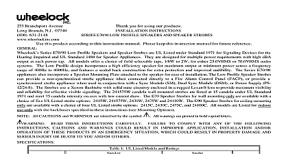
273 Branchport Avenue Branch N J 07740 631 2148 Thank you for using our products SERIES E70 24MCW MULTI CANDELA SPEAKER STROBE INSTRUCTIONS this product according to this instruction manual Please keep this instruction manual for future reference Series E70 24MCW Multi Candela Speaker Strobe is UL Listed under Standard 1971 for Signaling Devices for the Hearing for indoor fire protection service The E70 24MCW is designed for multiple power requirements with high dBA output at power tap and offers a choice of field selectable taps 1 8W to 2W for either 25.0VRMS or 70.0VRMS audio systems The Low design incorporates a high efficiency speaker for maximum output at minimum power across a frequency range of 400Hz to and features a sealed back construction for extra protection and improved audibility The E70 24MCW Multi Candela provides selectable light output intensities in one unit and incorporates a Speaker Mounting Plate attached to the speaker for ease of The Low Profile Speaker Strobe can provide a non synchronized strobe appliance when connected directly to a Fire Alarm Panel FACP or provide a synchronized strobe appliance when used in conjunction with a Sync Module SM Dual Sync DSM or the PS 12 24 8 Power Booster The Strobes use a Xenon flashtube with solid state circuitry enclosed in a rugged lens to provide maximum visibility and reliability for effective visible signaling The E70 24MCW is Listed for indoor use wall only with the backboxes specified in these instructions see Mounting Options All CAUTIONS and WARNINGS are identified by the symbol All warnings are printed in bold capital letters READ THESE INSTRUCTIONS CAREFULLY FAILURE TO COMPLY WITH ANY OF THE FOLLOWING CAUTIONS AND WARNINGS COULD RESULT IN IMPROPER APPLICATION CANDELA SETTING AND OR OPERATION OF THESE PRODUCTS IN AN EMERGENCY SITUATION WHICH COULD RESULT IN DAMAGE AND SERIOUS INJURY OR DEATH TO YOU AND OR OTHERS 1 UL Listed Models and Ratings at 10 Feet Watts The strobe will produce 1 flash per second over the Regulated Voltage range The E70 24MCW is UL Listed for indoor use with a temperature range of 32 cid 176 F to 120 cid 176 F 0 cid 176 C to 49 cid 176 C and maximum humidity of RH THE UL LISTED REGULATED VOLTAGE RANGE IS 16.0 33.0 VOLTS USING EITHER FILTERED DC OR FULL WAVE RECTIFIED VOLTAGE FWR THIS APPLIANCE WAS NOT TESTED OUTSIDE THE 16.0 LIMITS BY UL CHECK THE MINIMUM AND MAXIMUM OUTPUT OF THE POWER SUPPLY AND STANDBY AND SUBTRACT THE VOLTAGE DROP FROM THE CIRCUIT WIRING RESISTANCE TO DETERMINE THE VOLTAGE TO THE STROBE SPEAKERS THE VOLTAGE APPLIED TO THESE PRODUCTS MUST BE WITHIN THEIR RATED INPUT VOLTAGE RANGE APPLICATION OF IMPROPER VOLTAGE MAY RESULT IN DEGRADED OPERATION OR DAMAGE TO THESE WHICH COULD RESULT IN PROPERTY DAMAGE AND SERIOUS INJURY OR DEATH TO YOU AND OR 2000 Wheelock Inc All rights reserved E 1 of 8 CANDELA SETTING WILL DETERMINE THE CURRENT DRAW OF THE PRODUCT 2 Strobe Current Ratings AMPS for 24VDC Average Current RMS Peak Current Time duration of Strobe Peak Current is 1 millisecond Strobe Inrush Current is less than Rated Peak Current MAKE SURE THAT THE TOTAL AVERAGE CURRENT AND TOTAL PEAK REQUIRED BY ALL APPLIANCES ARE CONNECTED TO THE SYSTEM PRIMARY AND SECONDARY POWER SOURCES NAC CIRCUITS SM DSM MODULES OR THE PS 12 24 8 POWER BOOSTER DO NOT EXCEED THE POWER SOURCES RATED CAPACITY OR CURRENT RATINGS OF ANY FUSES ON THE CIRCUITS TO WHICH THESE APPLIANCES ARE WIRED OVERLOADING SOURCES OR EXCEEDING FUSE RATINGS COULD RESULT IN LOSS OF POWER AND FAILURE TO ALERT DURING AN EMERGENCY WHICH COULD RESULT IN PROPERTY DAMAGE AND SERIOUS INJURY OR TO YOU AND OR OTHERS calculating the total average or peak currents Use Table 2 to determine the highest value of Average Current for an strobe across the expected operating voltage range of the strobe or the highest value of Peak Current whichever higher of an individual strobe across the expected voltage range of the strobe then multiply the value by the total number of be sure to add the currents for any other appliances including audible signaling appliances powered by the same source and any required safety factors the peak current exceeds the power supplies inrush capacity the output voltage provided by the power supplies may drop below the voltage range of the appliances connected to the supply and the voltage may not recover in some types of power supplies For an auxiliary power supply that lacks filtering at its output stage either via lack of capacitance and or lack of battery backup the output may exhibit this characteristic The Speaker Strobe is not designed to be used on coded systems in which the applied voltage is cycled on and off E 2 of 8 DISTRIBUTION in deg Min 15cd UL Min Typ 30cd UL Min Typ 75cd Min 110cd 3A Horizontal Plane 0 5 0 5 3B Vertical Plane in deg Min 15cd UL Min Typ 30cd UL Min Typ 75cd Min 110cd E 3 of 8 E 4 of 8 INFORMATION doubling of rated Watts increases sound output by 3 dBA Field selectable input terminals are provided on each unit The wattage selections are available 1 8W 1 4W 1 2W 1W and 2W Frequency range of speakers is 400 4000Hz A 1.5mF blocking capaci tor for DC supervision of a