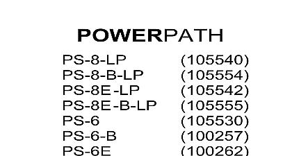
Wheelock POWERPATH PS-EXP expansion module install sheet P85011

File Preview
Click below to download for free
Click below to download for free
File Data
| Name | wheelock-powerpath-ps-exp-expansion-module-install-sheet-p85011-6521078493.pdf |
|---|---|
| Type | |
| Size | 1.38 MB |
| Downloads |
Text Preview
105534 EXTENDER ACCESSORY Instructions Branchport Avenue Long Branch NJ 07740 6899 Ph 800 631 2148 Fax 732 222 8707 Site www coopernotification com 2015 Cooper Wheelock Inc dba Cooper Notification All rights reserved F you for using our products this product according to this instruction manual keep this instruction manual for future reference OF CONTENTS INTRODUCTION AND SPECIFICATIONS INTRODUCTION SPECIFICATIONS TERMINOLOGY INSTALLATION INSTRUCTIONS UNPACKING MOUNTING WIRING SETTING THE DIP SWITCHES CONTROL PC BOARD TROUBLE CONDITION PRIORITY IDENTIFICATION TROUBLESHOOTING TROUBLE MODE GROUND FALUT DETECTION MODE OPERATION EXAMPLES LIST OF COMPATIBLE AUXILIARY DEVICES LIST OF COMPATIBLE NAC DEVICES WARRANTY STATEMENT 1 PS 8 Enclosure Layout 2 PS 6 Enclosure Layout 3 PS 8 Mounting Dimensions 4 PS 6 Mounting Dimensions 5 PS EXP PCB Board 6 Control PC Board Trouble LED Locations 7 NAC Extender Wiring with PS EXP OF FIGURES 1 Control PC Board Terminal Identification 2 PC Board DIP Switch Settings 3 Control PC Board LED Trouble Indicators 4 Control PC Board Trouble Priority Identification 5 Expansion Board Trouble LED OF TABLES 3 3 4 5 6 6 6 8 10 10 12 13 13 14 15 23 24 26 5 6 7 8 9 12 14 9 10 12 12 13 F 2 of 26 All CAUTIONS and WARNINGS are identified by the symbol All warnings are printed in bold capital letters THIS INSTRUCTION MANUAL CAREFULLY FAILURE TO COMPLY WITH ANY OF THE FOLLOWING INSTRUCTIONS AND WARNINGS COULD RESULT IN IMPROPER APPLICATION AND OR OPERATION OF THESE PRODUCTS IN EMERGENCY SITUATION WHICH COULD RESULT IN PROPERTY DAMAGE AND SERIOUS INJURY OR DEATH TO YOU OTHERS INTRODUCTION AND SPECIFICATIONS INTRODUCTION POWERPATH PS Expansion Board PS EXP is available as an accessory for the PS 6 PS 8 PS 8 LP PS 6E PS 8E PS 8E LP products PS EXP offers additional independently configurable power outputs Primary applications include NAC expansion ADA requirements and auxiliary power to support system accessories This unit provides up to four 4 Class 2 Class or two 2 Class and one 1 Class Notification Appliance Circuits The PS EXP NAC outputs the audible silence feature NAC output is rated at 3.0 Amps Class B or 3.0 Amps Class A and can be programmed to generate a Code 3 Temporal Horn sound or a strobe output signal Total load for the PS 8 and PS 8 LP NAC circuits not exceed 8.0 Amps Total load for the PS 6 NAC circuits shall not exceed 6.0 Amps PS EXP NAC outputs can also be used as UL 1481 Compliant power supply outputs When configured this way the continuous current rating is 3 Amps per power supply output and 4 Amps maximum total current for all continuous power supply outputs When configured this way the power outputs will shut off during the AC loss trouble condition so won deplete the batteries PS EXP mounts onto a PS 6 PS 8 PS 8 LP PS 6E PS 8E or PS 8E LP Logic Board The PS EXP shares the Logic input signals including IN1 CC1 IN2 CC2 SBUS IN and SILENCE IN PS EXP contains its own separate diagnostic trouble indicators to facilitate the troubleshooting of field wiring All PS trouble conditions change the state of the Logic Board General Trouble Relay and Input Return Relays Notification horn strobes strobe and horns with synchronizing capability can be utilized with the PS EXP F 3 of 26 SPECIFICATIONS UL Listed 864 Standard for Control Units and Accessories for Fire Alarm Systems UL Listed 1481 Standard for Power Supplies for Fire Protective Signaling Systems California State Fire Marshal CSFM FPA 72 compliant Environmental Approved for indoor dry locations Inputs Two 2 12VDC or 24VDC NAC Initiating Circuits 8 33VDC at 5mA Two 2 Contact Initiating Circuits Accepts two Class or two Class circuit inputs NOTE These input connections are shared with the PS 6 8 8 LP or PS 6E 8E 8E LP Logic Board 24VDC power limited synchronized outputs Up to 50 NAC devices per output maximum line impedance 1.46 Ohms per Up to 8 Amps in alarm supply current for the PS 8 or PS 8 LP Up to 6 Amp in alarm supply current for the PS 6 Capable of four 4 Class B regulated outputs Maximum of 3 Amps on an output Capable of two 2 Class A regulated outputs Maximum of 3 Amps on an output Capable of one 1 Class A regulated outputs and two 2 Class B regulated outputs Maximum of 3 Amps on an Temporal Code 3 strobe synchronization or constant voltage outputs Built in Wheelock synchronization mode that can be fed to any or all of the output circuits Input and output can be synchronized with FOLLOWER mode Continuous duty NON RESETTABLE output configuration 4 Amps of maximum continuous duty current Maximum of 3 on an output for specific applications Continuous power outputs are not battery backed up Audible silence capability Filtered and electronically regulated output The PS EXP can be synchronized through the SBUS terminals See Chapter 5.0 beginning with Sheet 15 for Examples Compatible with PS 6 8 8 LP or PS 6E 8E 8e LP connected to a 12VDC or 24VDC Fire Alarm Control Panel FACP Signaling appliance loops are supervised and steered to either IN1 or IN2 10K Ohm 1 2 Watt Wheelock Model PSEOL End of Line Resistor EOLR for supervision of all outputs Common input and output trouble circuits Short circuit protection with auto reset Output status LED indicators Any PS EXP trouble will automatically change the state of the PS 6 8 8 LP or PS 6E 8E 8e LP General Trouble Relay Ground Fault Detection with the ability to detect ground faults on individual circuits Impedance 0 Ohms NAC Extender Accessory Current Draw for battery calculations Current Draw 0.035 Amps in standby and 0.055 Amps during alarm activation Operating Temperature Storage Temperature Humidity Non condensing 0 C to 49 C 32 F to 120 F 85 C 5 at 30 2 C 86 F 4 F C to 70 C 4 F to 158 F


