Wheelock RSS colored lens strobe install sheet P84517

File Preview
Click below to download for free
Click below to download for free
File Data
| Name | wheelock-rss-colored-lens-strobe-install-sheet-p84517-6302791845.pdf |
|---|---|
| Type | |
| Size | 661.86 KB |
| Downloads |
Text Preview
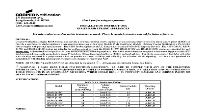
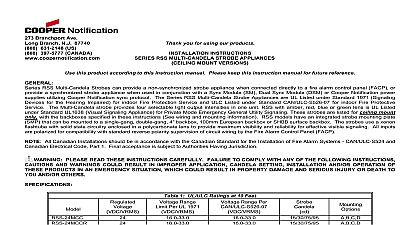
Branchport Ave Branch N J 07740 631 2148 Thank you for using our products INSTRUCTIONS RSSA RSSB RSSG RSSR STROBE APPLIANCES this product according to this instruction manual Please keep this instruction manual for future reference RSSA RSSB RSSG RSSR Strobes can provide a non synchronized strobe appliance when connected directly to a fire alarm control panel FACP or provide a strobe appliance when used in conjunction with a Sync Module SM Dual Sync Module DSM or Wheelock power supplies with patented sync protocol RSS strobes are intended for ceiling mount or wall mount with the backboxes specified in these instructions See Mounting Options The RSS models have an strobe mounting plate SMP that can be mounted to a single gang double gang 4 backbox 100mm European backbox or SHBB surface backbox The uses a xenon flashtube with solid state circuitry enclosed in a polycarbonate lens to provide maximum visibility and reliability for effective visible signaling All are polarized for compatibility with standard reverse polarity supervision of circuit wiring by an FACP PLEASE READ THESE INSTRUCTIONS CAREFULLY FAILURE TO COMPLY WITH ANY OF THE FOLLOWING CAUTIONS AND WARNINGS COULD RESULT IN IMPROPER APPLICATION INSTALLATION AND OR OPERATION OF THESE IN AN EMERGENCY SITUATION WHICH COULD RESULT IN PROPERTY DAMAGE AND SERIOUS INJURY OR DEATH TO YOU OTHERS CANDELA SETTING WILL DETERMINE THE CURRENT DRAW OF THE PRODUCT 1 Models and Ratings DC RMS VDC Draw FWR Current Draw Candela is measured on axis The candela settings are rated for clear lens derate approximately 25 for amber 55 for green 70 for blue and 80 for red All strobes operate from 16 to 33 volts at 1 flash second using filtered or full wave rectified DC voltage All models are for indoor use with a temperature range of 32 to 120 0 to 49 and maximum humidity of 85 RH The effect of shipping and temperatures shall not adversely affect the performance of the appliance when it is stored in the original cartons and is not subjected to misuse or CHECK THE MINIMUM AND MAXIMUM OUTPUT OF THE POWER SUPPLY AND STANDBY BATTERY AND SUBTRACT THE DROP FROM THE CIRCUIT WIRING RESISTANCE TO DETERMINE THE APPPLIED VOLTAGE TO THE STROBES Strobes are not designed to be used on coded systems in which the applied voltage is cycled on and off MAKE SURE THAT THE TOTAL AVERAGE RMS CURRENT REQUIRED BY ALL APPLIANCES THAT ARE CONNECTED TO THE PRIMARY AND SECONDARY POWER SOURCES APPLIANCE CIRCUITS SM AND DSM SYNC MODULES DO NOT EXCEED THE SOURCES RATED CAPACITY OR THE CURRENT RATINGS OF ANY FUSES ON THE CIRCUITS TO WHICH THESE APPLIANCES ARE OVERLOADING POWER SOURCES OR EXCEEDING FUSE RATINGS COULD RESULT IN LOSS OF POWER AND FAILURE TO ALERT DURING AN EMERGENCY WHICH COULD RESULT IN PROPERTY DAMAGE AND SERIOUS INJURY OR DEATH TO YOU OTHERS calculating the total currents Use Table 1 to determine the highest value of Average RMS current for an individual strobe across the expected operating voltage of the strobe Then multiply the value by the total number of strobes be sure to add the currents for any other appliances including audible signaling appliances by the same source and include any required safety factors AND MOUNTING INFORMATION 2007 Cooper Wheelock Inc All rights reserved P84517 M 1 of 4 The following figures show the maximum number of field wires conductors that can enter the backbox used with each mounting option If these are exceeded there may be insufficient space in the backbox to accommodate the field wires and stresses from the wires could damage the product the limits shown for each mounting option comply with the National Electrical Code NEC Cooper Wheelock recommends use of the largest backbox option and the use of approved stranded field wires whenever possible to provide additional wiring room for easy installation and minimum stress on the product from MOUNTING STD SINGLE GANG BACKBOX 2 DEEP 6 32 SCREWS OR SURFACE MOUNT 4 SQ X 1 1 2 DEEP BACKBOX OR 100mm X 37.5mm EUROPEAN BACKBOX STROBE MOUNTING PLATE 8 32 SCREWS MOUNTING PLATE NUMBER OF CONDUCTORS 18 AWG 16 AWG 14 AWG 12 4 4 4 OR SURFACE MOUNT DOUBLE GANG X 2 1 4 DEEP BACKBOX 6 32 SCREWS PLATE NUMBER OF CONDUCTORS 18 AWG 16 AWG 14 AWG 12 4 4 4 MOUNTING SURFACE SHBB MOUNTING SCREWS MOUNTING PLATE NUMBER OF CONDUCTORS 18 AWG 16 AWG 14 AWG 12 4 4 4 4 PLATE NUMBER OF CONDUCTORS 18 AWG 16 AWG 14 AWG 12 4 4 4 2 Wiring Diagrams 3 PRECEDING FACP SYNC MODULE NEXT SIGNAL END OF LINE EOLR VISIBLE VISIBLE VISIBLE UNISON PRECEDING FACP SYNC MODULE TO NEXT APPLIANCE OR EOLR VISIBLE PRECEDING FACP SYNC MODULE PRECEDING FACP SYNC MODULE TO NEXT APPLIANCE OR EOLR TO NEXT APPLIANCE OR EOLR strobe appliances have in out wiring terminals that accepts two 12 18 American Wire Gauge AWG wires at each screw terminal leads 3 8 inches and connect to screw terminals all in out wire runs on supervised circuits to assure integrity of supervision as shown in Figure 3 Strobe Plate assembly has red leads and two black leads for in out wiring The polarity in the wiring diagrams is for the operation of the appliances polarity is reversed by the FACP during supervision to the instruction sheets for SM P83123 DSM P83177 or Wheelock supplies for additional information P84517 M 2 of 4 PROCEDURES Check that the installed product will have sufficient clearance and wiring room prior to installing backboxes and conduit especially if sheathed cable or 3 4 conduit fittings are used RSS model can be flush mounted to a standard single gang backbox Figure A 4 or 100mm backbox Figure B or double gang backbox Figure C It can be surface mounted to a 4 or 100mm backbox Figure B double gang backbox Figure C or the SHBB Figure D Mounting hardware for each mounting is supplied Conduit entrances to the backbox should be selected to provide sufficient wiring clearance for the installed product Do not pass additional wires used for other the signaling appliance through the backbox Such additional wires could result in insufficient wiring space for the signaling appliance When terminating field wires do not use more lead length than required Excess lead length could result in insufficient wiring space for the appliance Use care and proper techniques to position the field wires in the backbox so that they use minimum space and produce minimum stress on the product This is important for stiff heavy gauge wires and wires with thick insulation or sheathing RSS model has an integrated Strobe Mounting Plate SMP which must be oriented correctly when it is mounted to the backbox Turn the SMP so that the above the words Strobe points to the top side Mount the SMP first to the backbox Next slide the beauty plate over the SMP until the 2 snaps of the beauty plate engage with the SMP beauty plate can be removed from the strobe assembly once engaged First gently insert a screwdriver into one of the slots located on the top and bottom edges the beauty plate Second gently pull away from the wall with the inserted screwdriver to disengage the snap Third repeat the first and second steps for the slot Finally gently lift the beauty