Wheelock SA-S speakers install sheet

File Preview
Click below to download for free
Click below to download for free
File Data
| Name | wheelock-sa-s-speakers-install-sheet-2698054317.pdf |
|---|---|
| Type | |
| Size | 689.41 KB |
| Downloads |
Text Preview
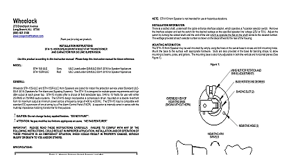
273 Branchport Ave Branch N J 07740 631 2148 PRECEDING OR PANEL AUDIO NEXT SIGNAL END 0F LINE 1 SA Speaker Wiring Diagram Shown with optional Strobe Wiring must be all power limited or all non power limited Reverberant dBA is a minimum UL rating based on sound measurements in a reverberant test room The SA Speaker is not designed to be used on coded systems in which the applied voltage is cycled on and off This appliance does not generate a temporal pattern signal If the distinctive three pulse temporal pattern Fire Alarm Evacuation or evacuation in accordance with NFPA 72 is required the control unit must be used with appliances that can generate the pattern signal Refer to manufacturer instruction manual for details INSTRUCTIONS SELF AMPLIFIED SPEAKER OR CEILING MOUNT this product according to this instruction manual Please keep this instruction manual for future reference Supervised Self Amplified SA Speaker is UL Listed under Standard UL1480 Speakers for Fire Alarm and Signaling Systems The Speaker is for indoor fire protection service and provides a choice of 6 different sound output levels and operates with audio input of 0.5 V RMS and 25 V RMS by means of selectable switch settings The Low Profile design incorporates a high efficiency for maximum output at minimum power across a frequency range of 400Hz to 4000Hz and features a sealed back construction extra protection and improved audibility All inputs are polarized for compatibility with standard reverse polarity supervision of circuit via a Control Panel SA Speaker appliance is listed for indoor use with the backboxes specified in these instructions see Mounting Options The SA will flush mount onto a 4 square deep backbox with an extension ring or surface mount using the SBB backbox Do not change factory applied finishes NOT PAINT DIAGRAMS DC Input Voltage DC Input Current Input Level Input Impedance 0.5V setting Input Impedance 25V setting 1 Specifications square grille SA S90 round grille 33.0 VDC 24 Amps RMS maximum V RMS or 25 V RMS field selectable Table 3 than 400 Ohms or equivalent to less than 1 1000 W 0.001 W 1 mW load than 20 kOhms or equivalent to less than 1 32 W 0.03125 W 31.25 mW load 1 to 6 field selectable Table 4 Use Only 32 to 122 0 to 50 93 RH 2A Speaker Sound Pressure Level Ratings Audio In Audio In dBA at 10Ft per UL1480 2B Directional Characteristics 50 degrees horizontal 50 degrees vertical 55 degrees horizontal 55 degrees vertical calculating the total currents Use Table 1 to determine the highest value of Current for an individual appliance then these values by the total number of appliances be sure to add the currents for any other appliances powered by the same source include any required safety factors sure that the total RMS current required required by all appliances that are connected to the system PRIMARY and SECONDARY sources NAC circuits DSM Sync Modules or Wheelock Power Supplies does not exceed the power sources rated capacity or the ratings of any fuses on the circuits to which these appliances are wired the minimum and maximum output of the power supply and standby battery and subtract the voltage drop from the circuit wiring to determine the applied voltage to the appliance P84502E 2020 Cooper Wheelock Inc dba Cooper Notification 1 switch on the PCB SW1 is used to select the input voltage and sound output level see Figure 3 OPTIONS A Flush Mount with 4 Square Box Ext Ring B Surface Mount with SBB 2 2 3 4 W 1 4 3 HERE FOR 0N HERE FOR OFF A SMALL SCREWDRIVER TO THE SWITCH POSITION 1 2 3 4 3 Audio Input Voltage Mode Selection Input Voltage Mode Settings SW1 V RMS V RMS 1 Output Level Settings SW1 4 Sound Output Level Selection typical typical Reference typical typical typical typical typical 4 3 2 settings are not to be used in UL Listed applications and should be used in non UL Listed applications only when the input level is not at the rated value 0.5 V RMS for the 0.5 V mode and 25 V RMS for the 25 V mode to provide 3 or 6 dB for line losses and or low drive levels Using these settings while applying the rated audio input to the will cause excessive distortion and increased current consumption and it is not a recommended operating is the setting used as a reference level for the other settings in Table 4 are typical values with respect to the reference level Sound Output Level 6 0 dB and are included only to assist the user choosing a setting during installation However use the values in Table 2A not these values for the actual sound output following figures A B show the maximum number of field wires conductors that can enter the backbox used with each mounting If these limits are exceeded there may be insufficient space in the backbox to accommodate the field wires and stresses from the could damage the product that the installed product will have sufficient clearance and wiring room prior to installing backboxes and conduit especially if multiconductor cable or 3 4 conduit fittings are used Number of Conductors 18 AWG 16 AWG 14 AWG 12 8 8 8 Number of Conductors 18 AWG 16 AWG 14 AWG 12 8 8 8 method shall be in accordance with In the United States the National Electrical Code NFPA 70 and the National Fire Alarm and Signaling Code NFPA 72 PROCEDURES a mounting option and install the backbox Screws are provided Conduit entrances to the backbox should be selected to sufficient wiring clearance for the installed product Do not pass additional wires used for other than the signaling through the backbox Such additional wires could result in insufficient wiring space for the signaling appliance appliance settings are correct for your application Set SW1 to match your Audio Input Voltage Table 3 and Output Sound Table 4 field wiring to the appliance When terminating field wires do not use more lead length than required Excess lead length result in insufficient wiring space for the appliance Do not pass additional wires used for other than the signaling appliance the backbox Such additional wires could result in insufficient wiring space for the signaling appliance care and proper techniques to position the field wires in the backbox so that they use minimum space and produce minimum on the product This is especially important for stiff heavy gauge wires and wires with thick insulation or sheathing correct orientation for SA speaker mounting The Speaker Mounting Plate must be oriented correctly when it is mounted to backbox Turn the Speaker Mounting Plate so that the arrow above the arrows and word are on the top side of the Mounting Plate the Speaker to the backbox Next slide the grille over the Speaker and attach with 2 screws not over tighten screws or terminals Excessive torque may affect operation When using power tools ensure the torque is to the lowest setting available Final acceptance is subject to Authorities Having Jurisdiction the installation instructions of the manufacturers of other equipment used in the system for any guidelines or restric