Wheelock SAFEPATH SP-SVC supervised volume control install sheet P84598

File Preview
Click below to download for free
Click below to download for free
File Data
| Name | wheelock-safepath-sp-svc-supervised-volume-control-install-sheet-p84598-6180593724.pdf |
|---|---|
| Type | |
| Size | 681.15 KB |
| Downloads |
Text Preview
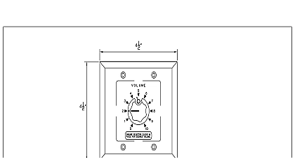
273 Branchport Ave Branch N J 07740 631 2148 Thank you for using our products INSTRUCTIONS SAFEPATH SUPERVISED VOLUME CONTROL this product according to this instruction manual Please keep this instruction manual for future reference SP SVC Supervised Volume Control is a 35 watt volume attenuator that is listed under UL864 for installation with the Safepath SP40S with the SPB 160 SPB 80 4 or SPB 320 It can be used to control the volume of a single speaker multiple speakers or an entire audio up to 35 watts The SP SVC contains an override relay that will bypass the attenuator when the system is put into an alarm condition allowing the emergency notification message s to be announced at the maximum volume The SP SVC is designed to be compatible a UL864 listed 24 volt supervised notification appliance circuit NAC It is compatible with class B wiring and with class A wiring if used the SP4 APS Addressable Paging Splitter This model is recommended for use with 70.7VRMS supervised audio systems but it can be used in 25.0VRMS systems if the load is reduced to 4 watts All CAUTIONS and WARNINGS are identified by the symbol All warnings are printed in bold capital letters PLEASE READ THESE INSTRUCTIONS CAREFULLY FAILURE TO COMPLY WITH ANY OF THE FOLLOWING CAUTIONS AND WARNINGS COULD RESULT IN IMPROPER APPLICATION INSTALLATION AND OR OPERATION THESE PRODUCTS IN AN EMERGENCY SITUATION WHICH COULD RESULT IN PROPERTY DAMAGE AND SERIOUS INJURY OR TO YOU AND OR OTHERS 1 Attenuation Rating dB dB Approx loss is less than 0.5 dB 2 Audio Power Rating Input Voltage VRMS VRMS Load 3 DC input ratings voltage VDC VRMS RMS Current mA 2011 Cooper Wheelock Inc dba Cooper Notification All rights reserved G 1 of 7 INFORMATION PRECEDING APPLIANCE NAC OUTPUT NEXT APPLIANCE OR EOLR AUDIO OUTPUT OR SPEAKER NEXT SPEAKER 1 Terminal Block wiring diagram SPB AUDIO OUT IN ALM COM 2 Typical system layout with SP40S and SPB Audio Booster and optional splitter Only one SP SVC can be installed per audio zone however multiple units can be controlled by the same NAC All fixed volume speakers must be placed before the SP SVC in the audio circuit Any speakers placed after the unit will be able to attenuated the SP SVC is installed in a supervised audio system with class B wiring then an end of line resistor EOLR must be installed on last speaker connected to the volume control unit Attach wires according to the label on the terminal block The DC input output terminals are interchangeable If the SP SVC is the unit on the NAC then an end of line resistor must be installed The maximum wire impedance between devices shall not exceed 35 ohms The SP SVC is not designed to be used on coded systems in which the applied voltage is cycled on and off G 2 of 7 LISTED OHM EOLR LISTED OHM EOLR LISTED OHM EOLR AUDIO SPEAKERS AND OR LISTED 10K OHM EOLR SPB 160 PC BOARD IN OUT OUT OUT OUT OUT OUT OUT 24VDC and EXP OUT wiring Non Power Limited Run these at least 1 4 from Power wiring and 1 4 above the Board WITH TWO SPLITTERS 3 Class B system wiring diagram SP4Z A B splitter is optional G 3 of 7 1 2 BOOSTER CLASS A 1 1 LISTED OHM EOLR EX2 VDC FOR BOTH SPLITTERS NAC CLASS A B B AUDIO VOLTAGE CLOSED 70Vrms OPEN 25Vrms SPB 160 PC BOARD IN OUT OUT OUT OUT OUT OUT OUT 4 Class A system wiring diagram SP4 APS Splitter is required SP SVC DC input must be connected to WITH TWO SPLITTERS A NAC G 4 of 7 LISTED OHM EOLR OUT OUT SUP OUT OUT IN 5 Installation with SP40S ONLY This installation option will result in loss of alarm contact closure to the following product manuals for additional wiring and installation information SPB 80 4 LISTED OHM EOLR G 5 of 7 INFORMATION the limits shown for each mounting option comply with the National Electrical Code NEC Cooper Notification recommends use of largest back box option shown and the use of approved stranded field wires whenever possible to provide additional wiring room for easy and minimum stress on the product from wiring The back box must be UL listed RING Check that the installed product will have sufficient clearance and wiring room prior to installing back boxes and conduit if sheathed multiconductor cable or 3 4 conduit fittings are used The SP SVC can be mounted to a 3 deep double gang box Figure A or a 4 inch square 1 deep box with a 1 extension and double gang ring Figure B Conduit entrances to the back box should be selected to provide sufficient wiring clearance for the installed product When terminating field wires do not use more lead length than required Excess lead length could result in insufficient wiring space the appliance Do not pass additional wires through the back box Such additional wires could result in insufficient wiring space the device Verify that the SP SVC is oriented correctly before wiring Position the unit so that the number 5 is at the top The terminal block can accept 8 wires from 12 to 18 AWG with one wire per each position Strip wires of an inch Insert the into the terminal block and turn the screws tightly to secure the wires If using stranded wire use care when inserting the to ensure that the wires do not fray and cross with the other wires Carefully push the unit into the back box Use care and proper techniques to position the field wires in the back box so that they use space and produce minimum stress on the product If using rigid heavy gauge wires it may be necessary to pre bend the so that the unit can be easily pushed into the back box the mounting screws through the holes in the cover plate and fasten them Verify correct installation by testing the unit and the system in background music mode and alarm mode MATERIAL EXTRAPOLATED FROM THIS DOCUMENT OR FROM COOPER NOTIFICATION MANUALS OR OTHER DOCUMENTS THE PRODUCT FOR USE IN PROMOTIONAL OR ADVERTISING CLAIMS OR FOR ANY OTHER USE INCLUDING OF THE PRODUCT APPLICATION OPERATION INSTALLAT


