Wheelock SAFEPATH SP4-APS addressable paging splitter install sheet P84577

File Preview
Click below to download for free
Click below to download for free
File Data
| Name | wheelock-safepath-sp4-aps-addressable-paging-splitter-install-sheet-p84577-4368109275.pdf |
|---|---|
| Type | |
| Size | 906.50 KB |
| Downloads |
Text Preview
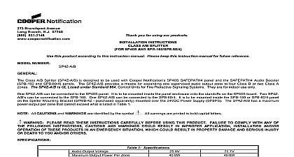
Branchport Avenue Branch N J 07740 631 2148 Thank you for using our products INSTRUCTIONS PAGING SPLITTER SP40S SPB 160 SPB 80 4 AND SPB 320 this product according to this instruction manual Please keep this instruction manual for future reference 109920 SP4 APS NUMBER GENERAL Addressable Paging Splitter module SP4 APS is designed to be used with Wheelock SP40S SAFEPATH panel and SP4 TZC Zone Controller The SP4 APS can also be mounted in SAFEPATH Audio Booster SPB 160 SPB 80 4 and panels The SP4 APS provides a means for expanding one supervised audio output zone to four Class B or two A supervised zones The SP4 APS also provides two expansion outputs that can be used to add additional audio modules in Class A or B configuration The SP4 APS is UL Listed under Standard 864 Control Units for Fire Signaling Systems It is for indoor use only SP4 APS can be mounted inside the SP40S panel The use of the Splitter Mounting Bracket SPMB4Z is required mounting the SP4 APS splitter s inside the Audio Booster panels Addressable Paging Splitter module SP4 APS is also used to expand and distribute supervised telephone paging and music to selected zones when the SAFEPATH system is not in the alarm condition When the SAFEPATH is in the alarm condition all telephone paging and background music inputs are silenced and the emergency message broadcast on all zones The SP4 APS is used with the Telephone Zone Controller SP4 TZC and controls the distribution the telephone paging and background music functions Use of the Telephone Zone Controller SP4 TZC is supplementary SP4 APS contains 16 LED indicators used to monitor and troubleshoot the module to the Installation Instructions for the Telephone Zone Controller SP4 TZC P84567 when connecting the SP4 APS for telephone paging and background music operation All CAUTIONS and WARNINGS are identified by the symbol All warnings are printed in bold capital PLEASE READ THESE INSTRUCTIONS CAREFULLY BEFORE USING THIS PRODUCT TO COMPLY WITH ANY OF THE FOLLOWING INSTRUCTIONS CAUTIONS AND WARNINGS RESULT IN IMPROPER APPLICATION INSTALLATION AND OR OPERATION OF THESE IN AN EMERGENCY SITUATION WHICH COULD RESULT IN PROPERTY DAMAGE AND INJURY OR DEATH TO YOU AND OR OTHERS SPECIFICATIONS SP4 APS has a maximum power output per zone that cannot exceed what is listed in Table 1 1 SP4 APS Specifications Input Power Zone Ground Fault 20k Ohms total audio power output from all zones on the SP4 APS cannot exceed the audio input power J 1 of 14 2009 Cooper Wheelock Inc dba Cooper Notification All rights reserved J 2 of 14 2.1 WIRING SPECIFICATIONS Size All terminal blocks accept 12 18 American Wire Gauge AWG for single wire connection WIRING INSTRUCTIONS The terminal blocks on the SP4 APS are removable To remove a terminal block pull the block straight up from board as shown in Figure 1 Attach wires to the desired connections then plug the terminal block back on the board careful to match and align the pins 2 shows the PC board layout with the locations of all terminal blocks 1 Removable Terminal Block EX2 VDC JP1 70Vrms 25Vrms 2 SP4 APS PC Board for the RS 485 connections are used with the SP4 TZC and are explained in the SP4 TZC installation instructions AUDIO ZONE OUTPUT WIRING SP4 APS can be configured for either A or B It cannot do both at the same time The maximum power output on any zone is 40 watts Expansion EX1 EX2 terminals follow the Class A or B setting that applies to zones of speakers up to four SPB 160 or SPB 80 4 or two SPB 320 Audio Boosters may be connected to an audio output provided that nothing else is on that zone The total number of Audio Boosters combined shall not exceed 33 Factory setting is for Class B Wiring A Audio Wiring an installation requires A audio field wiring on the SP4 APS module the Class Selector Switch SW2 be set for A Note that no end of line resistors UL Listed 10K Ohm EOLR are used on any of SP4 APS module audio output zones as shown in Figure 3 Zones Z1 and Z2 are connected in Class A as well as Z3 and Z4 Figure 3 shows the SP4 APS with SW2 and the audio field wiring set for J 3 of 14 audio zone outputs are either 25Vrms or 70.7Vrms matching the audio input voltage Remember the SP40S has a audio output to the splitter of 40 watts while the Audio Boosters have a maximum audio output to the splitter 80 watts J 4 of 14 circuit is not used jumper to negative and positive positive EX2 VDC JP1 70Vrms 25Vrms 3 A Zone Connections unused A zone must be jumpered negative to negative and positive to positive If the Expansion EX1 terminals are not used jumpers are required See Figure 3 B Audio Wiring an installation requires B audio field wiring the Addressable Paging Splitter module Class Selector SW2 must be set for B Note that end of line resistors UL Listed 10K Ohm EOLR are at the end of each audio output zone even if no speakers are present on a zone End of line resistors are on the EX1 and EX2 connections whether they are used or not Figure 4 shows the SP4 APS set for CLASS B field wiring audio zone outputs are either 25Vrms or 70.7Vrms matching the audio input voltage Remember the SP40S has a audio output to the splitter of 40 watts while the Audio Boosters have a maximum audio output to the SP4 of 80 watts circuits are terminated with an Listed 10K Ohm EOLR EX2 VDC JP1 70Vrms 25Vrms 4 B Zone Connections J 5 of 14 OTHER WIRING Expansion Circuit Wiring Expansion Circuits EX1 EX2 are used to link additional audio booster panels SPB 160 SPB 80 4 and SPB 320 the SP4 APS The audio zone outputs are either 25Vrms or 70.7Vrms matching the audio input voltage EX1 EX2 are current limited outputs If an over current condition is detected the affected Expansion Zone s will their audio output When the over current condition has been cleared and the affected Expansion Zone s go to condition the audio output will be re enabled To ensure that current limiting works properly for JP1 must be open for 70Vrms JP1 must be closed SPB 160 and SPB 80 4 enclosures contain one audio module while the SPB 320 contains two The SP40S has a maximum audio output to the splitter of 40 watts the Audio Boosters have a maximum audio output to the splitter of 80 watts Each audio booster module to the expansion circuits uses 1.2 watts There is a limit of 33 Audio Boosters that can be connected to an using SPB 160 or SPB 80 4 models Each SPB 320 counts as two SPB 160 models wiring of