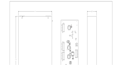
Wheelock SAFEPATH SP4-RMX remote microphone expansion module install sheet P84557

File Preview
Click below to download for free
Click below to download for free
File Data
| Name | wheelock-safepath-sp4-rmx-remote-microphone-expansion-module-install-sheet-p84557-4178936025.pdf |
|---|---|
| Type | |
| Size | 776.18 KB |
| Downloads |
Text Preview
273 Branchport Avenue Branch NJ 07740 631 2148 Thank you for using our products INSTRUCTIONS MICROPHONE EXPANSION MODULE this product according to this instruction manual Please keep this instruction manual for future reference NUMBERS 109919 Remote Microphone Expansion Module SP4 RMX is an outboard expansion module for use with the Safepath system It is used to expand the number of optional Microphones SPRM or SPRM GP to three The PCB assembly is mounted in an enclosure THESE INSTRUCTIONS CAREFULLY BEFORE USING THIS PRODUCT All CAUTIONS and WARNINGS are identified by the symbol All warnings are printed in bold capital letters Out Panel In 1 Out 2 In 3 1 Out 2 3 Speakers Audio SPB In Out MIC 1 In 2 3 These Remote Mics must be SPRM GP Page Remote Mic They are NOT be used for emergency paging Capabilities of the SP4 RMX 2009 Cooper Wheelock Inc dba Cooper Notification All rights reserved P84557 F Sheet 1 of 14 1 SP4 RMX modules can be ganged together when connecting them to an SP40S panel This provides a maximum of six remote providing Call for the entire system One SP4 RMX can be connected to each audio booster providing three non page remote microphones for that audio booster audio output Each SP4 RMX provides a line level 600 Ohm auxiliary input are two configurations for the Priority levels of the remote microphones can be set One configuration sets the priorities as priority 1 RM2 priority 2 and RM3 priority 3 For instance if RM3 is broadcasting RM1 or RM2 can override RM3 The configuration allows the first remote microphone to broadcast to have the top priority until it completes its message The remote operate on a first in first out basis SPECIFICATIONS K1 and K3 2A 30Vdc 1pF K2 K4 K5 and K6 1A 30Vdc 1pF 52mA max RM Page 62mA max Standby Remote Microphone Relay Ratings Current Auxiliary Audio Input Min Ground Fault Voltage 20k Ohms 24 VDC 1Vrms Dimensions H x W x D 13.0 x 7.6 x 2.15 33cm x 19.4cm x 5.4cm Weight Mounting 3.8 pounds 1.7kg 0.050 Steel Black Surface Mount Top and Bottom Wiring Entry UL requirements Operating Temperature 32 to 120.2 F 0 to 49 C Temperature to 158 F 20 to 70 C Humidity 85 30 C Non condensing lives of people depend upon your safe installation of the SP4 RMX Please read understand and follow the specific instructions set forth below to avoid damage to the SP4 RMX and equipment connected to it Installation should be only by qualified persons in accordance with procedures in this manual SHUT OFF ALL POWER BEFORE STARTING THE INSTALLATION ELECTRICAL SHOCK CAN DEATH OR SERIOUS INJURY P84557 F Sheet 2 of 14 The SP4 RMX printed circuit board is sensitive to static electricity and has delicate components mounted on it handling either a board or any component on a board discharge any static electricity from your body by touching a grounded such as a metal screw which is connected to earth ground Handle the board by its edges and be careful not to twist or flex it the SP4 RMX in a static free area and the user is to properly attach grounded wrist straps before touching any static sensitive After handling printed circuit boards the SP4 RMX should be tested in accordance with the Checkout section to that the printed circuit boards are undamaged and functioning properly The Authority Having Jurisdiction AHJ should be consulted by the installer prior to installation GUIDELINES 1 Prepare a drawing of the complete system wiring Keep copies of the system wiring drawing and this SP4 RMX Installation with the SAFEPATH panel for reference These Installation Instructions shall be made available to all qualified who operate test maintain or service SAFEPATH products 2 Carefully unpack the SP4 RMX and make sure each item described on the packing slip is present and undamaged 3 Mount the SP4 RMX in the desired location as described in the Mounting section 4 Mount any additional wiring boxes or junction boxes needed to interconnect field wiring 5 Connect conduit fittings or bushings as needed using knockouts provided on the top and bottom of the SP4 RMX units see 6 Install field wiring in conduit when necessary following the National Electrical Code and local codes for the type of system installed Make all necessary connections at any additional wiring or junction boxes Provide proper strain relief for all wiring not in conduit 7 Connect the SP4 RMX to earth ground following the National Electrical Code and local codes for the type of system being 8 Check the integrity of all field wiring following the directions in the Field Wiring Checkout section Confirm that the cable is installed and that there is continuity between required points no open circuits with no unwanted connections to other conductors chassis or earth ground 9 Connect the wiring to the appropriate terminals of the SP4 RMX modules following the directions in the Field Wiring section the system wiring drawing you created in Step 1 Set the switches for the proper configuration as described in the sections 2 P84557 F Sheet 3 of 14 GUIDELINES shielded twisted pair wire for all audio input and output wiring Follow national and local regulations for conduit use shield of each cable should be connected only at one end Each shield of each cable that connects to the SP4 RMX is to connect the grounding terminal provided near the right edge of the chassis see Figure 2 All SP4 RMX wiring should be routed away from any high voltage or high current lines such as AC or DC power audio power lines and motor or relay actuation lines and should be installed in separate conduit from high voltage or high lines National Electrical Code defines two types of circuits for protective signaling systems power limited circuits and non power circuits All SP4 RMX circuits have been designed as power limited circuits Do not run power limited and non power in the same conduit 20 Feet 14 22 AWG Shielded One end of the shield must be connected at the Safepath panel or SP4 RMX enclosure The National Electric Code limits the maximum number of conductors that can be installed in conduit and wiring depending on the size of the conduit the volume of the boxes and the gauge of the wire used Make sure that wiring used with the latest NEC requirements for power limited circuits SPECIFICATIONS SP40S or Audio Booster and SP4 RMX Cable Size Maximum Length Restrictions each SPRM and SP4 RMX Cable Size Maximum Length Maximum Capacitance SP4 RMX shall be mounted in a location within the environmental limits specified in the latest UL Standard for indoor control It shall not be located in a hazardous location Refer to the Technical Specifications section wiring between SP40S or Audio Booster and SP4 RMX must be run in conduit and within the same room used with the SPB 160 SPB 80 4 or SPB320 the RMX must be located in the same room 14 22 AWG Shielded The shield must be connected only at the SP4 RMX


