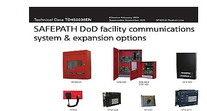
Wheelock SAFEPATH SP40S in-building communications system install sheet P84714

File Preview
Click below to download for free
Click below to download for free
File Data
| Name | wheelock-safepath-sp40s-in-building-communications-system-install-sheet-p84714-3845126907.pdf |
|---|---|
| Type | |
| Size | 1.97 MB |
| Downloads |
Text Preview
Facility System Testing and Manual Number P84714 Number A84715 001 2018 Cooper Wheelock dba Cooper Notification All Rights Reserved P C Multi Function Facility Communications System 2 Cooper Notification Notification fulfills its mission of People Take Action by high quality and advanced and services for the life safety and security markets Notification has served the of commercial educational health care and government for more than eighty five years the company continues to focus designing and manufacturing technological products to the world needs for Emergency Management and Notification Communications and Notification more information contact Notification Branchport Avenue Branch NJ 07740 6899 800 631.2148 732 222.2588 Site www coopernotification com info coopernotification com Multi Function Facility Communications System 3 Multi Function Communication System Forward of Contents use 13 Design Change Disclaimer 13 User Operation Assistance 13 Product Model Descriptions 13 Typographical Notation Conventions 13 Read This Manual 15 Operational Safety 15 Expected Equipment Lifecycle 16 Periodic Testing 16 Compliance with Applicable Codes Regulations Laws Standards and Safety Precautions Overview 16 Recommendation 17 Audio Output Considerations 17 RF Interference 18 General 18 Compatibility with Existing Safepath Products 19 Standard Features 19 Enclosure and Configuration 21 Nominal Electrical Data 21 User Interface 22 Basic Operation of User Interface 23 Overview 23 Additional Drawings 25 User Settings 30 Switch Descriptions 30 Jumper Descriptions 32 LED Descriptions 33 Installation 34 Fire Alarm Control Panel Wiring Applications 34 General Installation Instructions 35 Preparing the System Wiring Diagram 38 Unpacking and Taking Inventory 38 Locating the Panel 38 Installing Field Wiring Connections 40 Installing Strobe Connections 41 Installing Audio Output Connections 42 Installing Auxiliary Circuit Connections 43 Multi Function Communication System Installing Audio Input Connections 43 Installing Digital Voice Initiating Connections 43 Installing Ancillary Audio Input Connections 43 Setting Adjustable Audio BGM Sources 45 Installing Alarm System Trouble and AC Trouble Output 45 Wiring the System 46 Wiring Guidelines 46 Field Wiring Connections 47 Preparing a System Wiring Diagram 47 Visual Notification Appliance Output Wiring 47 Speaker Notification Appliance Output Wiring 48 Wiring Diagrams for Audio Visual Notification Appliances 48 Wiring the Alarm Output Contact 49 Wiring the System Trouble Connections 50 Performing System Checkout 50 System Control Settings 50 Checkout Procedure 51 Ground Fault Detection 53 Battery Care and Backup Battery Calculations 53 Caring for Sealed Lead Acid Batteries 53 Storing Batteries 54 Calculating Backup Battery Requirements 54 AC Power and Batteries 55 Installing AC Power 55 Installing Batteries 56 58 User Interface 58 Supervision 58 Visual Notification Appliance Output Circuit Supervision 59 Audio Notification Appliance Output Circuit Supervision 59 Amplifier Supervision 59 Ground Fault Supervision 59 Actions that Initiate Audio Alarms 59 Making Live Announcements 60 Recording Digital Voice Messages 60 Recording Messages on the Digital Voice Section 61 Verifying Messages


