Wheelock SAFEPATH SP4Z-A B audio booster splitter install sheet P84205

File Preview
Click below to download for free
Click below to download for free
File Data
| Name | wheelock-safepath-sp4z-a-b-audio-booster-splitter-install-sheet-p84205-9371806542.pdf |
|---|---|
| Type | |
| Size | 759.80 KB |
| Downloads |
Text Preview
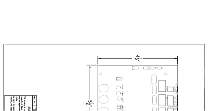
Branchport Avenue Branch N J 07740 631 2148 Thank you for using our products INSTRUCTIONS A B SPLITTER SP40S AND SPB 160 SPB 80 4 this product according to this instruction manual Please keep this instruction manual for future reference SP4Z A B NUMBER Class A B Splitter SP4Z A B is designed to be used with Cooper Notification SP40S SAFEPATH4 panel and the SAFEPATH4 Audio Booster and SPB 80 4 panels The SP4Z A B provides a means for expanding one supervised audio output zone to four Class B or two Class A The SP4Z A B is UL Listed under Standard 864 Control Units for Fire Protective Signaling Systems They are for indoor use only SP4Z A B can be connected to the SP40S panel It is to be mounted inside the panel enclosure onto the standoffs on the SP40S board Two SP4Z can be connected to the SPB 160 One SP4Z A B can be connected to the SPB 80 4 It is to be mounted inside the SPB 160 or SPB 80 4 panel the Splitter Mounting Bracket SPMB 4Z purchased separately mounted over the 24VDC Power Supply SPBPS The SP4Z A B has a maximum output per zone that cannot exceed what is listed in Table 1 All CAUTIONS and WARNINGS are identified by the symbol All warnings are printed in bold capital letters PLEASE READ THESE INSTRUCTIONS CAREFULLY BEFORE USING THIS PRODUCT FAILURE TO COMPLY WITH ANY OF FOLLOWING INSTRUCTIONS CAUTIONS AND WARNINGS COULD RESULT IN IMPROPER APPLICATION INSTALLATION AND OR OF THESE PRODUCTS IN AN EMERGENCY SITUATION WHICH COULD RESULT IN PROPERTY DAMAGE AND SERIOUS INJURY DEATH TO YOU AND OR OTHERS 1 Specifications A B Output Voltage Output Power Per Zone Voltage Current at 24VDC Ground Fault Sensitivity Output Power Per Zone K Ohms INSTRUCTIONS The terminal blocks on the SP4Z A B are removable To remove a terminal block pull the block straight up from the circuit board as shown in 1 Attach wires to the desired connections then plug the terminal block back on the board being careful to match and align the pins 1 Removable Terminal Block 2011 Cooper Wheelock Inc dba Cooper Notification All rights reserved T 1 of 9 INSTRUCTIONS 2 shows the mounting location of the SP4Z A B Splitter to the SP40S panel Figure 3 shows the correct mounting procedure SP4Z A B STUDS 2 Location SCREW 4 COVER STANDOFFS 4 PC BOARD STANDOFFS 4 PC BOARD ENCLOSURE Mounting in SP40S Enclosure 3 4 standoffs through the SP40s board to the 4 mounting studs of the SP40S enclosure Position the SP4Z A B PC board with the terminal blocks pointing to the top of the SP40S enclosure and align the mounting holes on the PC board the mounting studs Screw the male end of the 4 cover standoffs through the SP4Z A B PC board and to the 4 standoff installed in Step 1 Tighten standoffs snug Attach wiring in accordance with the wiring section of this installation instruction Align the SP4Z A B cover with the holes in the cover standoffs and mount the cover using the 4 mounting screws Tighten the screws hand tight T 2 of 9 and SPB 80 4 INSTRUCTIONS 4 shows the mounting location of the SP4Z A B Splitter to the Splitter Mounting Bracket SPMB 4Z purchased separately Figure 5 shows the mounting procedure POWER SUPPLY MOUNTING SPMB 4Z B WIRING B WIRING A WIRING A WIRING Mounting Location for the SPB 80 4 and SPB 160 4 COVER BOARD 6 32 SCREW HEX M F SPACER SP4Z A B MTG BRKT 8 32 KEPS NUT Diagram for SP4Z A B Splitter and SPMB 4Z Mounting Bracket 5 Mount the Splitter Mounting Bracket SPMB 4Z to the SPB 160 or SPB 80 4 according to installation instructions P84252 Position the SP4Z A B PC board with the terminal blocks pointing to the top of the Audio Booster enclosure and align the mounting holes on the PC with the mounting studs Screw the male end of the 4 Hex M F Spacers through the SP4Z A B PC board and to SPMB 4Z Tighten standoffs snug plus turn Attach wiring in accordance with the wiring section of this installation instruction Align the SP4Z A B Cover with the holes in the cover spacers and mount the cover using the 4 mounting screws Tighten the screws hand tight Repeat Steps 2 through 6 when installing second splitter in the SPB 160 Audio Booster One SPMB 4Z mounting bracket can support two SP4Z A B splitters INSTRUCTIONS SHUT OFF ALL POWER BEFORE STARTING THE INSTALLATION ELECTRICAL SHOCK CAN CAUSE DEATH OR SERIOUS Do not move jumpers while the unit is powered on Doing so may damage the Splitter Plugs J1 and J3 must be set for either Class A or Class B Wiring Figures 6A and 6B Factory setting is for Class B Wiring T 3 of 9 6A Setup for Class A Wiring 6B Setup for Class B Wiring See Figures 6C and 6D for wiring diagram Unused zones must have a Listed 10K Ohm EOLR installed to prevent an open trouble condition Cannot utilize Class A and Class B wiring on single splitter See Figure 8 or the Splitter cover silkscreen for terminal block wiring designations A WIRING SPB 160 SPB 80 4 IN LISTED 10K OHM EOLR TERMINATION IF NOT USED LISTED 10K OHM EOLR 6C Power Limited For Supervised Class A Wiring SPB 160 SPB 80 4 IN LISTED OHM EOLR TERMINATION IF NOT USED LISTED 10K OHM EOLR 6D Power Limited For Supervised Class B Wiring B WIRING SHUT OFF ALL POWER BEFORE STARTING THE INSTALLATION ELECTRICAL SHOCK CAN CAUSE DEATH OR SERIOUS T 4 of 9 ZONE 24VDC Splitter power run at least 1 4 above top of the SP 40S board BOARD SHUT OFF ALL POWER BEFORE STARTING THE INSTALLATION ELECTRICAL SHOCK CAN CAUSE DEATH OR SERIOUS Routes for Wiring the SP4Z A B to the SP40S 7A T 5 of 9 ZONE AUD1 and AUD2 run at least 1 4 from 24VDC wire run Splitter output wire run least 1 4 above the top of splitter circuit board SUPPLY IN OUT OUT OUT OUT OUT OUT OUT IN RET IN RET IN RET Routes for Wiring the SP4Z A B to the SPB 160 to the AUD1 and AUD2 Splitters SHUT OFF ALL POWER BEFORE STARTING THE INSTALLATION ELECTRICAL SHOCK CAN CAUSE DEATH OR SERIOUS 7B 24VDC Splitter power run at least 1 4 above top of the SPB 160 board BOARD the Audio Output wiring the right side and to the of the enclosure then the bottom to the left of the enclosure up the side and to the AUD IN of the splitter T 6 of 9 ZONE AUD1 and AUD2 run at least 1 4 from 24VDC wire run Splitter output wire run least 1 4 above the top of splitter circuit board SUPPLY IN OUT OUT OUT OUT OUT OUT OUT IN RET IN RET IN RET