Wheelock SAFEPATH SPRM remote microphone install sheet P84207

File Preview
Click below to download for free
Click below to download for free
File Data
| Name | wheelock-safepath-sprm-remote-microphone-install-sheet-p84207-2817503496.pdf |
|---|---|
| Type | |
| Size | 670.01 KB |
| Downloads |
Text Preview
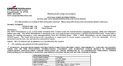
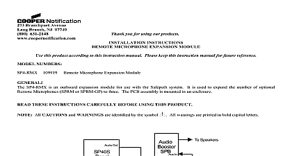
Branchport Avenue Branch NJ 07740 631 2148 Thank you for using our products INSTRUCTIONS REMOTE MICROPHONE FOR USE WITH SP40S this product according to this instruction manual Please keep this instruction manual for future reference 108996 109932 SPRM SPRM B NUMBER Remote Microphone is UL Listed under Standard 864 Control Units for Fire Protective Signaling Systems They are Listed for use only The Remote Microphone is designed to be used with Wheelock SP40S SAFEPATH Panel It provides a means for emergency voice announcements from an auxiliary location Only 1 Remote Microphone can be connected to the SP40S The hand held push to talk microphone is supervised to ensure proper connection It is not repairable If it is detached from unit the unit must be returned for repair All CAUTIONS and WARNINGS are identified by the symbol All warnings are printed in bold capital letters PLEASE READ THESE INSTRUCTIONS CAREFULLY BEFORE USING THIS PRODUCT FAILURE TO COMPLY ANY OF THE FOLLOWING INSTRUCTIONS CAUTIONS AND WARNINGS COULD RESULT IN IMPROPER INSTALLATION AND OR OPERATION OF THESE PRODUCTS IN AN EMERGENCY SITUATION WHICH RESULT IN PROPERTY DAMAGE AND SERIOUS INJURY OR DEATH TO YOU AND OR OTHERS Input Voltage Output Level Impedance Ground Fault Current DIAGRAM 1 shows the proper wiring connections for connecting the SPRM to the SP40S 24VDC 1.05V RMS 600 Ohms 20k Ohms Standby 23mA Alarm 30mA PANEL IN OUT CC AUDIO 1 This wiring is power limited All wiring is supervised unless otherwise noted SPECIFICATIONS Size Length Capacitance 0.1uF Total Run 50pF foot for 1000 FT 2009 Cooper Wheelock Inc dba Cooper Notification All rights reserved American Wire Gauge AWG Shielded The shield must be connected only at the SP40S Panel Feet F 1 of 4 INSTRUCTIONS REMOTE MICROPHONE STATION STATUS INSTRUCTIONS Turn key to ON position Press microphone button speak into microphone GANG BACKBOX A KEY SCREW A 2 2 shows the proper mounting requirements for the SPRM Install a 4 gang backbox either flush or surface to the desired location Be sure that the mounting box is level Attach the 6 wires as shown in the wiring diagram Figure 1 Be sure to use the specified wire Attach the mounting plate to the box with the 4 screws as shown in Figure 2 INSTRUCTIONS IN LED NAC CC 3 3 shows the locations of the switches and LED on the SP40S that require operation during operation and troubleshooting Set switch SW6 NAC CC to the CC position Set the jumper on J4 to the 1V position Remove the jumper on JP4 key and turned to the ON position for the controls to function The key is removable only in the OFF position IF JP4 JUMPER IS NOT REMOVED THE SP40S WILL NOT BE ABLE TO DETECT ANY REMOTE TROUBLE F 2 of 4 REMOTE MICROPHONE STATION STATUS TROUBLE INSTRUCTIONS Turn key to ON position Press microphone button speak into microphone 4 shows the SPRM front panel and the location of the LED The green and yellow LED s reflect the system condition regardless of the key position The green LED indicates there no faults in the SPRM The yellow LED indicates a trouble condition has occurred in the SPRM The red LED indicates the is ready to transmit the live voice of the operator 4 With the mouth one to two inches from the microphone press the microphone push to talk button and speak into the microphone deliver the live audible announcement SHOOTING yellow LED illuminates when there is a problem with the wiring between the SP40S wiring problems that can occur can be improper wiring reversed on the Audio connections and or CC connections This will provide a trouble condition on the SP40S panel with the system TROUBLE LED illuminated and the IN Auxiliary LED ON The SP40S internal sounder will also sound If checking and or correcting problems do not correct the trouble the SPRM should be replaced MATERIAL EXTRAPOLATED FROM THIS DOCUMENT OR FROM COOPER NOTIFICATION MANUALS OR DOCUMENTS DESCRIBING THE PRODUCT FOR USE IN PROMOTIONAL OR ADVERTISING CLAIMS OR ANY OTHER USE INCLUDING DESCRIPTION OF THE PRODUCT S APPLICATION OPERATION AND TESTING IS USED AT THE SOLE RISK OF THE USER AND COOPER NOTIFICATION WILL HAVE ANY LIABILITY FOR SUCH USE F 3 of 4 WARRANTY Cooper Wheelock Inc dba Cooper Notification and Cooper Notification Inc each a products must be used within their specifications and must be PROPERLY specified applied installed operated maintained and operationally tested in with these instructions at the time of installation and at least twice a year or more often and in accordance with local state federal codes regulations and laws Specification application installation operation maintenance and testing must be by qualified personnel for proper operation in accordance with all of the latest National Fire Protection Association Underwriter Laboratories UL National Electrical Code NEC Occupational Safety and Health Administration OSHA state county province district federal and other applicable building and fire standards guidelines regulations laws and codes but not limited to all appendices and amendments and the requirements of the local authority having jurisdiction AHJ products when properly specified applied installed operated maintained and operationally tested as provided above are against mechanical and electrical defects for a period of a three 3 years from date of manufacture with respect to MEDC Seller Industrial Signals and Seller Fire and Security Notification Appliances and Devices or b one 1 year from date of with respect to Waves and SafePath Voice Evacuation and Mass Notification Systems date of manufacture is by date code Correction of defects by repair or replacement shall be at Seller sole discretion and shall constitute of all obligations under this warranty THE FOREGOING LIMITED WARRANTY SHALL IMMEDIATELY IN THE EVENT ANY PART NOT FURNISHED BY SELLER IS INSTALLED IN THE PRODUCT THE LIMITED WARRANTY SPECIFICALLY EXCLUDES ANY SOFTWARE REQUIRED FOR THE OPERATION OR INCLUDED IN A PRODUCT SELLER MAKES NO REPRESENTATION OR WARRANTY OF ANY OTHER KIND IMPLIED OR STATUTORY WHETHER AS TO MECHANTABILITY FITNESS FOR A PARTICULAR PURPOSE ANY OTHER MATTER ARE SOLELY RESPONSIBLE FOR DETERMINING WHETHER A PRODUCT IS SUITABLE FOR THE USER OR WHETHER IT WILL ACHIEVE THE USER INTENDED RESULTS THERE IS NO WARRANTY DAMAGE RESULTING FROM MISAPPLIACATION IMPROPER SPECIFICATION ABUSE ACCIDENT OR OPERATING CONDITIONS BEYOND SELLER CONTROL DOES NOT WARRANT THAT THE OPERATION OF THE SOFTWARE WILL BE UNINTERRUPTED OR ERROR OR THAT THE SOFTWARE WILL MEET ANY OTHER STANDARD OF PERFORMANCE OR THAT THE OR PERFORMANCE OF THE SOFTWARE WILL MEET THE USER REQUIREMENTS SELLER SHALL BE LIABLE FOR ANY DELAYS BREAKDOWNS INTERRUPTIONS LOSS DESTRUCTION ALTERATION OR PROBLEMS IN THE USE OF A PRODUCT ARISING OUT OF OR CAUSED BY THE SOFTWARE LIABILITY OF SELLER ARISING OUT OF THE SUPPLYING OF A PRODUCT OR ITS USE WHETHER ON NEGLIGENCE OR OTHERWISE SHALL NOT IN ANY CASE EXCEED THE COST OF CORRECTING AS STATED IN THE LIMITED WARRANTY AND UPON EXPIRATION OF THE WARRANTY PERIOD ALL LIABILITY SHALL TERMINATE SELLER IS NOT LIABLE FOR LABOR COSTS INCURRED IN REMOVAL OR REPAIR OF A PRODUCT BY ANYONE OTHER THAN SELLER OR FOR DAMAGE OF ANY TYPE