Wheelock ST paging speaker install sheet P82595

File Preview
Click below to download for free
Click below to download for free
File Data
| Name | wheelock-st-paging-speaker-install-sheet-p82595-8729043165.pdf |
|---|---|
| Type | |
| Size | 717.99 KB |
| Downloads |
Text Preview
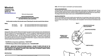
Branchport Avenue Branch N J 07740 631 2148 com Thank you for using our products INSTRUCTIONS SPEAKER WITH MULTI TAP TRANSFORMER this product according to this instruction manual Please keep this instruction manual for future reference ST H15 B ST H30 speakers should be used in large and or noisy locations They are weatherproof and may be used indoors or outdoors The of the variable transformer tap selector switch should be set to provide a sound output of at least 6dB for paging and 3dB for music above the background noise everywhere in the paging zone However the horn speaker volume should not be set high as to cause discomfort to those closest to the horn In some cases use of multiple horns set at lower volume provide better coverage than one horn set at full volume Horns should be mounted at least 15 feet above the floor and angled downward All CAUTIONS and WARNINGS are identified by the symbol All warnings are printed in bold capital letters READ THESE INSTRUCTIONS CAREFULLY FAILURE TO COMPLY WITH ANY OF THE INSTRUCTIONS CAUTIONS AND WARNINGS COULD RESULT IN IMPROPER APPLICATION AND OR OPERATION OF THESE PRODUCTS IN AN EMERGENCY SITUATION WHICH COULD IN PROPERTY DAMAGE SERIOUS INJURY OR DEATH TO YOU AND OR OTHERS Selector Switch Settings 1 2.0W 4.0W 7.5W 15.0W Not Used Not Used Not Used 1.0W 2.0W 3.8W 7.5W 15.0W Not Used Not Used Not Used Not Used 0.48W 0.94W 1.8W 7.5W 15.0W 4.0W 7.5W 15.0W 30.0W Not Used Not Used Not Used 2.0W 3.8W 7.5W 15.0W 30.0W Not Used Not Used 0.3W 0.5W 0.9W 1.9W 3.8W 6.9W 13.9W Power Handling Capacity RMS 15 Watts ST H15 B 30 Watts ST H30 2 Sound Dispersion 110 Degrees 3 Constant Line 25V 70V or 100V 4 Frequency Response 375 10,000Hz Full Rated Output 5 Sound Level At Rated Output 122dB SPL On Axis 1 Meter Rated Power 6 Sound Level At Rated Output ST H30 125dB SPL On Axis 1 Meter Rated Power Dimensions 8 15 16 Dia X 10 Dia Do not place switch in settings marked not used Failure to comply with these restrictions may cause damage to and will void the warranty 1993 1994 1995 2000 Wheelock Inc All rights reserved C 1 of 5 INFORMATION is a slotted shaft underneath the cable entrance interface adapter which operates a 7 position selector switch Remove the adaptor and set the switch for the desired wattage at the specified speaker line voltage 25V 70V or 100V Adjust the by turning the slotted shaft until the end of the slot which is opposite the flat on the shaft points to the desired number The provided at each selector number is shown on the decal affixed to the rear of the housing tables and the graphs shown below as a general guide to determine horn spacing area coverage and sound pressure level Noise Coverage To Moderate Noisy Horn Ft 64 32 2 Projection Side to Side Front to Rear Ft Ft Ft Ft 60 Ft 30 Ft Mounting Height is 15 20 Feet Typical Mounting Angle to Vertical is 60 degrees For very noisy locations above 96dB consult Wheelock for applications assistance from Horn Ft on Axis CAUTION The total system wattage requirement should not exceed 85 of the system amplifiers rated output The total wattage requirement is the summation of the wattage tap selections of all system speakers and horns from Horn Ft on Axis C 2 of 5 INFORMATION horn speakers may be wall mounted by simply using the holes in the swivel base to locate and drill mounting holes Mount the to the surface with appropriate hardware Slots are also provided in the base for banding straps to allow mounting to beams and girders The mounting base is also fully adjustable in both the vertical and horizontal planes See Figure 1 These devices are not intended for use in hazardous locations as defined by the National Electrical Code NEC and the National Fire Protection Association NFPA 1 Loosening the wing nut will allow for both pitch and rotation of the unit When adjusting horn position be careful not to lose adjusting hardware interface adapter mounted to the horn permits conduit connection The interface adapter is threaded for standard 1 2 pipe and accommodate BX cable flexible or rigid conduit and matching connectors The interface adapter is shown in Figure 2 below If interface adapter is not suitable for your installation then replace it with the clear plastic shield and 2 short mounting screws separately 2 C 3 of 5 INFORMATION the Interface Adaptor or clear plastic shield to expose the two 2 screw terminals and connect the audio installation wires as in Figure 3 The terminals are numbered 1 and 2 to indicate phasing which should be maintained throughout the systems example In an installation with multiple horns connect the same color audio wire to all number 1 terminals and another color wire to all number 2 terminals to ensure proper phasing as shown in Figure 4 Mount Interface Adapter or clear plastic shield on horn 3 Wiring 4 Typical Horn Connection to 25V 70V or 100V Line CHART Sound Wide Sound One Location Volume One Location 3 Cause And Correction paging horn wires at amplifier end and check whether amplifier is operational If repair amplifier wires from affected horn and substitute with known good horn If new horn the voice coil could be open If new horn does not operate check installation wiring selector switch setting for higher wattage Volume and Distortion Wide may not have the capacity to supply power to all horns Replace with a higher capacity amplifier Excessive bass energy can damage horn voice coils especially at high power levels To avoid possible damage an with a bass roll off filter horn protect circuit should be used Always operate audio amplifiers and speakers within their specified ratings Excessive input may distort sound and may damage audio equipment Do not exceed 130 of speaker input voltage Improper input voltage can damage If distortion is heard check for clipping of the audio appliance with an oscilloscope and reduce the amplifier input level or level to eliminate any clipping Check the installation instructions of the manufacturers of other equipment used in the system for any guidelines or on wiring and or locating Notification Appliance Circuits NAC and notification appliances Some system communication and or audio circuits for example may require special precautions to assure electrical noise immunity e g audio crosstalk MATERIAL EXTRAPOLATED FROM THIS DOCUMENT OR FROM WHEELOCK MANUALS OR OTHER DESCRIBING THE PRODUCT FOR USE IN PROMOTIONAL OR ADVERTISING CLAIMS OR FOR C 4 of 5 OTHER USE INCLUDING DESCRIPTION OF THE PRODUCT APPLICATION OPERATION INSTALLATION TESTING IS USED AT THE SOLE RISK OF THE USER AND WHEELOCK WILL NOT HAVE ANY LIABILITY SUCH USE READ SEPARATE GENERAL INFORMATION SHEET FOR INFORMATION ON THE PLACEMENT INSTALLATION FINAL CHECKOUT AND PERIODIC TESTING OF NOTIFICATION APPLIANCES Warranty products must be used within their published specifications and must be PROPERLY specified applied installed operated and operationally tested in accordance with these instructions at the t