Wheelock STH cluster speaker strobe install sheet P84730

File Preview
Click below to download for free
Click below to download for free
File Data
| Name | wheelock-sth-cluster-speaker-strobe-install-sheet-p84730-3726081495.pdf |
|---|---|
| Type | |
| Size | 687.70 KB |
| Downloads |
Text Preview
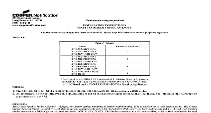
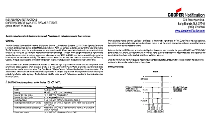
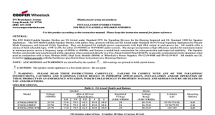
Branchport Avenue Branch N J 07740 631 2148 Thank you for using our products CLUSTER SPEAKER DUAL STROBE ASSEMBLY INSTRUCTIONS this product according to this instruction manual Please keep this instruction manual for future reference 1 Models 1 3 1 3 Color 2 Color of 2 Cluster Speaker Dual Strobe Assembly is designed for indoor ceiling mounting in high ambient noise level environments The Cluster Dual Strobe is a speaker visual alerting system that is equipped with 4 UL Listed STH 15SR supervised horn loudspeakers a UL Listed Strobe and a non UL approved 110 candela strobe with a colored lens mounted to a NEMA Type 1 galvanized steel enclosure X 10 L X 6 D The High Candela Strobe is mounted to a 3 9 16 deep backbox which is then mounted to the steel enclosure The and MCCH strobe are pre wired to the internal terminal block and the 110 candela strobe is connected to a pair of wire leads The can be wired for one or two speaker circuit operation The strobes are configured for connection to independent notification appliance NAC STH 15SR loudspeaker provides multiple power requirements with high dBA output at each power tap STH 15SR offers a choice of field taps 1 to 15 Watts for either 25VRMS or 70VRMS audio systems The Series STH design incorporates a compression driver mounted a double re entrant horn for maximum output at minimum power across a UL rated frequency range of 400 to 4,000Hz and an anechoic range of to 14,000Hz The speaker line inputs are compatible with standard supervision of circuit wiring by a Voice Control Panel A capacitor is wired series with the multi tap transformer for this purpose Each loudspeaker meets or exceeds the UL Standard 1480 Speakers for Fire Protective Systems RSS 24MCCH and RSS 110R G A B strobes can provide a non synchronized strobe signal when connected directly to a Fire Alarm Control FACP or provide a synchronized strobe signal when used in conjunction with a Sync Module SM or Dual Sync Module DSM The Appliances are UL Listed under Standard 1971 Emergency Devices for the Hearing Impaired for Indoor Fire Protection Service RSS 110R G A B models are not UL Listed The strobes use a xenon flashtube with solid state circuitry enclosed in a polycarbonate lens to maximum visibility and reliability for effective visible signaling All inputs are polarized for compatibility with standard reverse polarity of circuit wiring by a FACP additional information see the Installation Instruction Sheet for the STH 15SR P82697 and the RSS 24MCCH P84442 and Data Sheet for the RSS 110R G A B PLEASE READ THESE INSTRUCTIONS CAREFULLY FAILURE TO COMPLY WITH ANY OF THE INSTRUCTIONS CAUTIONS AND WARNINGS COULD RESULT IN IMPROPER APPLICATION INSTALLATION OPERATION OF THESE PRODUCTS IN AN EMERGENCY SITUATION WHICH COULD RESULT IN PROPERTY SERIOUS INJURY OR DEATH TO YOU AND OR OTHERS 2005 Wheelock Inc All rights reserved 1 of 4 INSTRUCTIONS WATTAGE SELECTOR SWITCH SETTING See Installation Sheet P82697 Remove the cable entrance interface adaptor and gasket Adjust the Speaker Wattage Selector Switch for the desired dB and wattage setting for each speaker Replace the cable entrance interface adaptor and gasket INSTRUCTIONS Loosen the 4 Phillips screws holding the cover plate and the RSS 24MCCH Strobe to the enclosure box See Figure 1 Remove the cover plate Mount the speaker assembly to the desired location Punch out desired knockouts and attach conduit and fittings Connect all field wiring as per wiring information in Figure 3 or 4 Replace cover plate to the enclosure box and tighten the 4 Phillips screws Adjust the angle for the speakers to point to the desired direction Be sure that the speakers do not block the strobe view See Figure 5 1 Phillips Screw Location and Strobe Numbering 2 Speaker Numbering PLATE STROBE 1 2 3 SCREW INFORMATION cid 54 cid 9 cid 54 cid 9 cid 55 2 Speakers Circuits 1 S2 3 Wiring Diagram for Two Audio Circuits 2 S4 PRECEDING SPEAKER AMPLIFIER NEXT CLUSTER OR OF LINE RESISTOR PRECEDING FIRE CONTROL FACP OR POWER SUPPLY NEXT APPLIANCE EOLR PRECEDING SPEAKER AMPLIFIER NEXT CLUSTER OR EOLR OUT OUT OUT 1 2 3 PRECEDING FIRE CONTROL FACP OR POWER SUPPLY CIRCUIT BE SYNCHRONIZED STROBE 2 CIRCUIT NUT NEXT APPLIANCE EOLR 2 of 4 PRECEDING SPEAKER AMPLIFIER PRECEDING FIRE CONTROL FACP OR POWER SUPPLY NEXT APPLIANCE EOLR NEXT CLUSTER OR OF LINE RESISTOR 4 Wiring Diagram for One Audio Circuits OUT OUT OUT 1 2 3 PRECEDING FIRE CONTROL FACP OR POWER SUPPLY CIRCUIT BE SYNCHRONIZED STROBE 2 CIRCUIT NUT NEXT APPLIANCE EOLR Strip leads 3 8 inches and connect to screw terminals Cluster Speaker Strobes have in out wiring terminals that accepts two 12 to 18 Wire Gauge AWG wires at each screw terminal Break all in out wire runs on supervised circuits to assure integrity of circuit supervision The polarity shown in the wiring diagram is for of the appliances The polarity is reversed by the Fire Alarm Control Panel FACP during supervision All models are for indoor use with a temperature range of 32 F to 120 F 0 C to 49 C and maximum humidity of 85 RH 5 Cluster Speaker Strobe Unit If Cluster Speaker Strobe assemblies are operated within 10 Feet of a person ear they can produce a sound pressure level that the maximum 120dBA permitted by NFPA and OSHA rules Exposure to such sound levels can result in damage to a person hearing Always operate audio amplifiers and speakers within their specified ratings Excessive input may distort sound quality and may audio equipment Do not exceed 130 of speaker input voltage per UL 1480 Improper input voltage can damage speaker If distortion heard check for clipping of the audio appliance with an oscilloscope and reduce the amplifier input level or gain level to eliminate any clipping 3 of 4 Check the installation instructions of the manufacturers of other equipment used in the system for any guidelines or restrictions on and or locating Notification Appliance Circuits NAC and notification appliances Some system communication circuits and or audio for example may require special precautions to assure electrical noise immunity e g audio cross talk MATER


