Ademco - 970 Analyzers (6v and 12v)

File Preview
Click below to download for free
Click below to download for free
File Data
| Name | ademco-970-analyzers-6v-and-12v-5129068743.pdf |
|---|---|
| Type | |
| Size | 1.40 MB |
| Downloads |
Text Preview
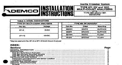
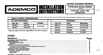
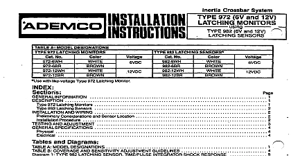
A MODEL DESIGNATIONS 970 ANALYZERS No be used with any Type 970 Analyzer PVDC 980.981 SENSORS No WH BR 2 970 Analyzers 980 Surface Mounted Sensors Mounted Sensors AND WIRING SPECIFICATIONS Considerations and Sensor Location Procedure 3 4 4 4 and Diagrams B COVERAGE AND SENSITIVITY ADJUSTMENT GUIDELINES 1 TYPE 970 ANALYZER TIME PULSE RESPONSE 5 2 TYPE 980 SENSOR INSTALLATION DETAILS 3 TYPE 981 SENSOR INSTALLATION DETAILS 4 TYPICAL SENSOR LOCATIONS 5 FIELD CONNECTIONS WITHOUT SEPARATE TAMPER LOOP 6 FIELD CONNECTIONS WITH SEPARATE TAMPER LOOP Inertia Crossbar System Type 970 Analyzers accommodzite any number of Type 980 and or 981 Sensors a maximum of 30 is recommended entry shock detection can be used alone or can complement other forms of perimeter protection The system possesses theability atjacks before an intruder gains entry to the premises the system functions A succession of small shocks a smaller number of largershocks a single will trip the analyzer and place it in alarm System reset is accomplished by interrupting momentarily unless optional automatic analyzer alarm contacts can be connected Type 970 Analyzers require 6VDC current 60ma for their operation The 12V models require 12VDC current Except where otherwise this way The analyzer will respond to blows applied to the surface s protected by the fault in the sensor analyzer any alarm panel possessing a closed circuit protective ease of servicing The resultant has been selected during herein applies information both types connection of a Two wire supervised sensor cirduit a tampered housing containing an LE visible through b separate tamper loop if required c protective circuit 970 Analyzers analyzer furnished adjustment potentiometer and terminals end of line alarm and d 6VDC power 12VDC as required Also provided automatic analyzer contains a processing circuit which has been designed for optimum response to at forced entry through most building materials See Diagram 1 The alarm trip IeLel is reached after the of a succession of light shocks e g gentle prying of a door or window ora smaller numberof heaviershocks hitting or pounding on the building structure A gross attack very large single shock or faGIt in the sensor will trip the system immediately The time pulse shocks such as may be caused by building expansion or contraction or other transient occurrences the analyzer trip level is reached its alarm contacts will open and its LED will light The unit will remain thus in until reset by momentary reset itself after about 5 seconds of power if optional automatic circuit provides good immunity a jumper which can be cut to select has been selected the system unit closed contacts open unit cover a level lower level 980 Surface Mounted Sensors sensor tampered housing contains a shock sensing module and terminals for connection of the two wire end resistor supervised sensor loop and if required a separate tamper loop The housing mounting sensing module may be rotated up to 180 about its axis to facilitate mounting on a vertical horizontal or sloping and to enable sensor operation of the mounting surface and other field conditions See Diagram 2 the heart of the sensing module is the inertia crossbar assembly A high inertia mass is mounted on a highly polished plated which straddles four other highly polished gold plated elements in such a manner as to provide parallel paths for the sensor circuit current with two sensing contact term and reliability are provided by this multiple path arrangement entry attempts assembly The resultant time pulse unit will go into alarm produce vibrations which affect the contact points of the sensing module a NORMAL or DAMPED mode depefiding upon range desired char sensor circuit current are then processed by the is sensed the trip level will be reached and a series of shocks of sufficient in each path Optimum and rapid variations designed NORMAL at top or DAMPED WIRING the analyzer sensor circuit No tamper is necessary as the sensor is a round molded housing The unit requires a diameter hole for mounting and a small dot on its at bottom mode of operation See Diagram 3 981 Flush Mounted Sensors Type 981 functions similarly the Type 950 Sensors but is designed for flush mounting on vertical surfaces only is particularly useful where aesthetic considerations are of prime importance such as in residences The unit is with two leads for connection enables orientation Considerations of the many types of building materials and construction methods used it is impossible to give