Ademco - 972 Latching Monitors

File Preview
Click below to download for free
Click below to download for free
File Data
| Name | ademco-972-latching-monitors-9162843750.pdf |
|---|---|
| Type | |
| Size | 1.39 MB |
| Downloads |
Text Preview
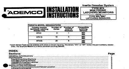
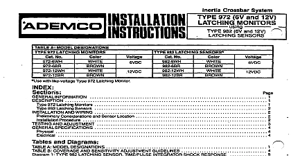
Inertia Crossbar System 986 Multisensor Latches Considerations and Sensor Location Procedure AND ADJUSTMENT and Diagrams A MODEL DESIGNATIONS B COVERAGE AND SENSlTlVlTY ADJUSTMENTGUIDELlNiS 5 1 LATCHING SENSOR TfME PULSE INTEGRATOR SHOCK RESPONSE 5 2 LATCHING SENSOR INSTALLATION DETAILS 6 3 SENSORS FOR USE WITH TYPE966 INSTALLATION DETAILS 6 4 TYPICAL SENSOR LOCATIONS 5 FIELD CONNECTIONS WITHOUT SEPARATETAMPER LOOP 7 7 6 FIELD CONNECTIONS WITH SEPARATETAMPER LOOP INFORMATION Inertia Crossbar System Type 972 Latching Monitors accommodate Latching Sensors or 966 Multisenscr The resultant perimeter protection The system possesses premises sensor sensitivity can be individually A succession of small shocks a smaller number of larger shocks or a single gross attack will trip and the sensor and in turn trip and latch the monitor and place it in alan A fault in the sensor loop will also the monitor A lit LED on the monitor and on each tripped sensor indicates monitors 972 Latching Monitors unit cover an alarm monitor and terminals connection of a Two wire supervised sensor circuit with end of line resistor b separate loop if required c protective circuit the unit closed contacts open during alarm d 614V DC power a sensor will light The unit will remain in alarm until reset by momentary ease of ser entry shock detection system can be used alone or can complement other forms contacts can be connected interrupting a tampered housing containing an LED visible through although a maximum of 30 is recommended the monitor alam contacts will open and its detect attacks before an intruder gains entry to any alarm panel possessing a closed circuit combination or quantity of Type level is reached and the monitor monitor power momentarily an alarm has occurred the surface area that it of power and will respond blows applied Table A Reset is furnished ability t h cover optimum other highly polished gold plated elements processing circuit which has been designed a NORMAL or DAMPED mode depending upon range desired the inertia crossbar assembly A high inertia mass is mounted on a highly produce vibrations which affect the contact points of the sensing module surface mounting An LED is visible through This allows connections lower level occasional shocks caused by building expansion or contraction be made in a less confined wired block the wires should be carefully dressed to avoid interference with the cover 985 LATCHING SENSORS sensor tampered housing contairis a shock sensing module a level sensitivity adjustment potentio and terminals connection of the two wire end of line resistor supervised sensor loop and if required a tamper loop The housing designed 985 Latching Sensor terminal blocks When replacing tamper switch or other components on the circuit board sensor contains a to attempts at forced entry through most building materials See Dia 1 The alarm trip level is 3 a door or window or a smaller after the sensing of a succession of light shocks e g gentle of heavier shocks e g hitting or pounding on the building structure A gross attack very large single including breaking of glass or fault in the sensor loop will trip the system immediately The time pulse circuit provides other transient occurrences module may be rotated up to 180 aboutits axis to facilitate mounting on a vertical horizontal or surface and to enable sensor operation of the mounting surface and other field conditions See Diagram 2 the heart of the sensing module gold plated which straddles to provide two parallel paths for the sensor circuit current with two sensing contact long term stability and reliability are provided by this multiple path arrangement entry attempts assembly The resultant time pulse will trip and its LED will light steadily The monitor system LED will light and the alarm will be signaled protective system control 986 MULTISENSOR LATCHES Type 986 contains processing circuits similar to those of the 985 It is also designed to accept an unlimited of 981 or 983 ICS sensors in addition it causes the trip The will latch and report an alarm to the 972 when any of the sensors connected the entire group of sensors all the en to be exceeded Since there is only a single trip level adjustment should be mounted on the same type of surface in the same vicinity so that one adjustment and they have approximately same diameter of protection The 986 reports the status of the entire group can not register which sensor was attacked For ease of servicing a maximum of 20 sensors are recommend for connection AND WIRING Considerations and Sensor Location of the many types of building materials and construction methods used it is impossible location that might be obtained under ideal conditions as shown number of sensors may be connected and ease of servicing The diameter of protection give precise the diameter of protection each sensor when mounted on various materials and ad sensor circuit current are then processed by the sen sensed the trip level will be reached the windows doors corners or joints between panels or cracks In these cases the sensors should be mounted 112 DP from the center of the gap See Diagram 4 a b c d Where the opening exceeds the DP use sensors the edge as shown a single 986 and total of 30 sensors to a single 972 SEE DIAGRAMS 2 and 3 a single monitor but a maximum of 30 is recommended its own sensing module and report attack on any one or more of any shock system Table B gives general guidelines may be smaller where there am discontinuities a series of shocks of sufficient in each path Op and rapid variations the mounting surfa such a manner Diagram 4 e optimum better Locate sensors at the most likely intrusion height relative to outside ground level