Ademco - 973 15 Zone Latching Monitors (6v and 12v)
File Preview
Click below to download for free
Click below to download for free
File Data
| Name | ademco-973-15-zone-latching-monitors-6v-and-12v-5824793106.pdf |
|---|---|
| Type | |
| Size | 1.47 MB |
| Downloads |
Text Preview
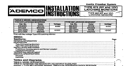
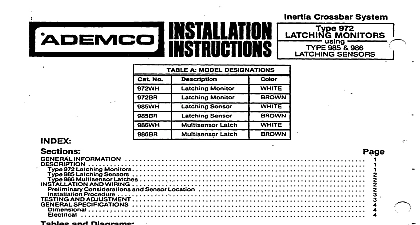
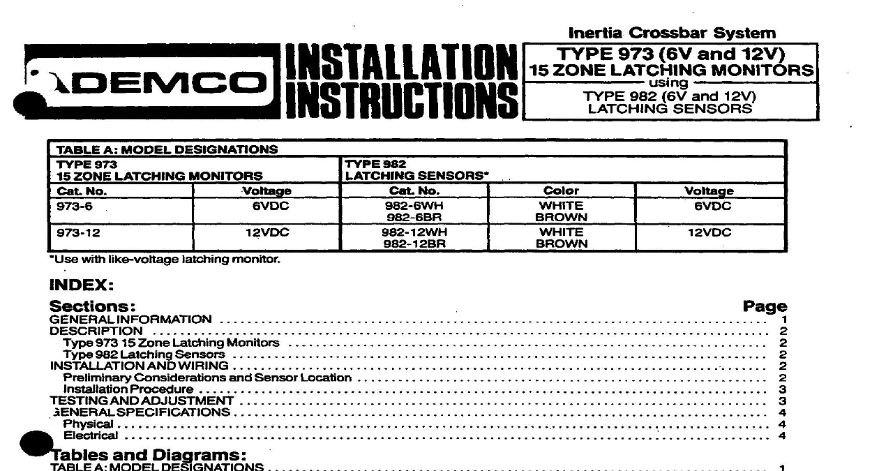
I A MODEL DESlGNATlONS 973 ZONE LATCHING MONITORS No with like voltage latching monitor SENSORS No PVDC AND WIRING Considerations and Sensor Location AND ADJUSTMENT and Diagrams A MODEL DESIGNATIONS B COVERAGE AND SENSlTIVITY ADJUSTMENT GUIDELINES 1 TYPE 982 LATCHING SENSOR TIME PULSE INTEGRATOR RESPONSE 2 TYPE 962 LATCHINGSENSOR INSTALLATION DETAILS 3 TYPICAL SENSOR LOCATIONS 4 FIELD CONNECTIONS WITHOUTSEPARATE TAMPER LOOP 5 FIELD CONNECTIONS WCTN SEPARATE TAMPER LOOP INFORMATION Inertia Crossbar System Type 973 15 Zone Latching Monitors can individually annunciate up to 15 like voltage Type Latching Sensors Addiinaf sensors may be connected if desired but without zone annunciation For ease of servfc a maximum total of 38 sensors including those that are zone annunciated is recommended resultant forced entry shock detection system can be used alone or can complement other forms of perimeter protec The system possesses the ability to detect attacks before an intruder gains entry to the premises sensor senskivky can be individually adjusted Blows applied to the surface area that is protected a succession of shocks a smaller number of larger attacks or a single gross attack will trip and latch the sensor and in turn trip and the monitor and place it in alarm LED above the reset switch on the monitor will light and so will the monitor individual zone LED s corre to the sensor s that tripped The LED on each tripped sensor will light as well to pinpoint the source s of alamt fauft in the sensor loop will trip the monitor and light its system LED but no zone or sensor LEDs will light When the fauft the monitor will restore and fts system LED will go out monitor SPDT alarm contacts can be connected into any protective circuit Reset is accomplished by momenta y the RESET swftcft on tfte face of the monitor 973 8 Monitor requires 6V DC 66 ma The 973 12 requires 12V DC 46 ma Current drain is not dependent on sensors are connected where otherwfse indicated the information contained her pplii 6V and 12V mdnitors and sensors 973 15 Zonk Latching Monitors monitor is composed of a two gang switch LED plate to which is mounted two bracket assemblies One bracket contains a monitor board with RESET switch tamper switch alarm relay and system LED and an annunciator containing 5 LEDs The other bracket assembly contains two annunciator boards each with 5 LEDs An end of line 1 K ohm is included for connection at the end of the sensor loop monitor board also contains terminals and leads for connection of Two wire supervised sensor circuit with end of line resistor b separate tamper loop if desired c protective circuit and DC power 6V or 12V as required See diagram 4 or 5 annunciator board also contains terminals for the connection of the zone leads from the individual sensors and power bracket assemblies are intended to be mounted in a standard two gang electrical box flush or surface and covered by accompanying switch LED plate 982 Latching Sensors sensor tampered housing contains a shock sensing module a level sensitivity adjustment potentiometer and for connection of the two wire end of line resistor supervised sensor loop and if required a separate tamper loop housing is designed for surface mounting An LED is visible through its cover sensor contains a integrator processing circuit whii has been designed for optimum response to at forced entry through most building materials See Diagram 1 The alarm trip level is reached after the sensing of succession of light shocks e g gentle prying of a door or window or a smaller number of heavier shocks e g hiing or on the building structure A gross attack very large single shock including breaking of glass or fault in the sensor will trip the system immediately The time pulse integrator circuit provides good immunity to lower level occasional such as may be caused by building expansion or contraction of other transient occurrenws sensing module may be rotated up to 166 about its axis to facilitate mounting on a vertical horizontal or sloping surface to enable sensor operation in a NORMAL or DAMPED mode depending upon range desired characteristics of the surface and other field conditions See Diagram 2 the heart of the sensing module is the inertia crossbar assembly A high inertia mass is mounted on a polished gold which straddles four other highly polished gold plated elements in such a manner as to provide two paral paths for the sensor circuit current with two sensing contact points in each path Optimum long term stability and reliilii provided by this multiple path arrangement e y attempts typically produce vibrations which affect the contact points of the sensing module inertia crowbar The resultant tiny and rapid variations in sensor circuit current are then procewed by the sensor time pulse If a series of shocks of sufficient intensity is sensed the trip level will be reached the unit will trip and its LED will steadily The monitor system LED and appropriate zone LED will light and the alarm will be signaled to the protective control AND WIRING Considerations and Sensor Location of the many types of building materials and construction methods used it is impossible to give precise sensor low information for any shock system but Table B gives general guidelines as to the diameter of protection DP that might obtained under ideal conditions for each sensor wften mounted on various materials and adjusted as shown to 15 Type 982 sensors may be connected to the Type 973 monitor wfth individual zone annunciation Addiinal sensors be connected if desired but without zone annunciation at the monitor For ease of seticing a maximum total of 30 sen including those that are zone annunciated is recommended Tha diameter of protection DP may be smaller whara thara are disco ultias tha molmtlng surlace such a doors wmers or joints between panels or cracks In these cases the sensors should be mounted at DP the center of the gap See Diagram 4 a b c d Where the opening exceeds the DR use sensors around the edge shown in Diagram 4 e Locate sansors at the most likely intrusion height fefatfve to outafde ground WeI Where the height of a wall 1 DR use two rows staggered as shown in Diagram 4 f Sensors onsurfaces below outside ground level require halt DP spacing Loose or rattling surfaces may give false shock signals In particular check windows for loose frames or panes Beams studs and electrical conduit incraaaa shock transmission For example when protecting roof areas take of the shock transmitting properties of beams Sensors on wlndow framas should ba locatad 2 or lass from glass zot should be foamted at feast 3 in from the frame See lnstaflation Procedure Step 4b for mounting