Ademco - RX360 Ceiling Mount Passive Infrared Detector

File Preview
Click below to download for free
Click below to download for free
File Data
| Name | ademco-rx360-ceiling-mount-passive-infrared-detector-1359067482.pdf |
|---|---|
| Type | |
| Size | 1.10 MB |
| Downloads |
Text Preview
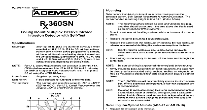
NOTE For U L Listed Requirements the coverage is 360 by 54 ft m when mounted from 10 to 13 ft 3.1 to 4.0 m using AR8 13 Array and when mounted from 15 to 18 ft 4.6 to m using the AR13 18 Array Power to 15.0 VDC 18 mA sure all wiring is unpowered de energized before routing Firmly mount the base Depending on local regulations the base may directly surface mounted using anchors mollies or wing nuts or be mounted to standard four inch octagonal or square electrical a location likely to intercept an intruder moving across the pattern See Typical Placements to Achieve Coverage The mounting height is 8 to 18 ft 2.4 to 5.5 m mounting surface should be solid and vibration free e g tiles should be secured if the area above the tiles is used an air return for HVAC systems Do not mount near air handling system outlets or in areas of extreme Remove the cover by turning it counterclockwise Remove the base from the enclosure by pressing the two enclosure tabs inward while lifting the enclosure away from the base rock the enclosure side to side during removal to the friction caused by the base to enclosure terminal Route wiring as necessary to the rear of the base and through the hole RX360 base will not completely cover a four inch square Where aesthetics are important a four inch octagonal box recommended to removable ceiling tiles is not recommended unless sandwich is made of the base ceiling tile and a back plate the tile Covers used for four inch octagonal and square make a suitable back plate when used with bolts and nuts as an example 12 97 Mount Passive Infrared Detector with Self Test by 60 ft 18.3 m diameter coverage when on eight to 18 ft 2.4 to 5.5 m high ceilings consists of 64 zones grouped into 16 barriers one additional zone looking straight down from unit sabotage Each barrier is 30 ft 9.2 m long 4.4 ft 1.3 m wide at 30 ft 9.2 m Choice of two modules depending on ceiling height Power is no internal standby battery Connect to DC sources capable of supplying standby power if power fails Eighteen mA H required for each of standby time needed Four hours 72 mA H are required for U L Listed Requirements selectable for Standard Intermediate or High Relay operating Form relay Contacts rated 125 28 VDC maximum for DC resistive loads Do not with capacitive or inductive loads Closed with cover in place tamper switch rated at 28 VDC 125 mA maximum Output solid state open collector conducts to terminal 1 the detector is in a trouble condition Maximum load is 25 mA storage and operating range is 20 to 120 to 50 For U L Listed Requirements the is 32 to 120 0 to 50 a Sonalert type sounder low voltage will pro an audible tone when the unit is in alarm Use of sounder is intended only as an aid for walk testing installation Sonalert is a trademark of Mallory 2 Internal View 1 Coverage Pattern 3 Enclosure the Optical Module AR8 13 or AR13 18 Replace the enclosure onto the base For ceilings between 8 and 13 ft 2.4 and 4.0 m from the floor use the module marked AR8 13 This marking can be found next to the optical module tabs ceilings between 13 and 18 ft 4.0 and 5.5 m high use the optical marked AR13 18 replace an optical module push the optical module tabs towards the until the module snaps free of the circuit board Holding the new by the tabs snap the new module into place fingerprints on the mirrored surfaces Should the mirrored sur become soiled or otherwise marked they can be cleaned using a clean cloth and any commonly available mild window cleaner Sensitivity The recommended setting for most installa Use in locations where an intruder is expected to cover only a portion of the protected area Tolerates normal environments on setting The detector is shipped in Intermediate Sensitivity High Sensitivity The setting for fast response to intruder signals For only in extremely quiet environments where ceiling drafts and ther and illumination transients are not anticipated both switches are in the OFF position the unit will default to the setting Although the sensitivity modes provide different degrees of to environmentally caused alarms the installer should peak background noise voltage readings do not exceed VDC Timer S4 and S5 switches S4 and S5 for the desired anti blocking timer time The is shipped with the anti blocking timer feature disabled APPLY POWER AFTER ALL CONNECTIONS BEEN MADE AND INSPECTED Gain Do not coil excess wiring inside unit Terminals 1 2 Power limits are 6 to 15 VDC Use no smaller 22 AWG 0.8 mm wire pair between the unit and the power Terminals 3 4 5 Alarm relay contacts rated 125 mA 28 VDC for DC resistive loads Use terminals 4 5 for Normally circuits Do not use with capacitive or inductive loads Terminals 6 7 Normally Closed tamper contacts rated at 28 VDC mA Terminal 8 Trouble Output Switch Settings RX360 has several features that are controlled using the configura switches RX360 permits selection of the signal gain depend upon the environment to be protected The gain jumper is located under the optical module High Gain Recommended for large coverage applications up to 60 ft m in diameter The RX360 is shipped in this setting If the gain jumper is missing the unit will default to High Gain Gain Recommended for applications where the area to be cov is 40 ft 12.2 m or less in diameter and for applications where Gain may be too sensitive for environmental extremes the RX360 for Low Gain reduces the coverage area to ft 12.2 m in diameter and Walk Testing Attach test leads to the Noise Voltage terminals The outside terminals common and the center terminal is positive Attach a Sonalert to the sounder pins at this time if one will be used walk testing The use of a Sonalert type device sounder will provide an tone during the time the unit is in alarm Of the three connector pins the center pin is positive with to either outside pin outside pins are common is a trademark of Mallory Place the cover on the unit and twist lock it clockwise into place sure the test leads and Sonalert leads are dressed the cutout Apply power to the unit Wait at least two minutes after applying power to start walk tests Walk testing should be done across the pattern as shown The edge of the coverage pattern is determined when Alarm Test LED indicator and Sonalert if in first turns on Walk test the unit from all directions to determine the ON Allows the Alarm Test LED to operate when activated by motion OFF The LED will not operate on alarm activation but will indicate a After completion of the walk tests remove the if installed Operation S1 trouble condition Mode S2 and S3 modes depend on the type of coverage desired and the environment Standard Sensitivity Tolerates environment extremes on this setting requires the largest amount of intruder motion to achieve an alarm 2 Tests Measurement Meter readings are very important in determining background levels and catch margin sensitivity Connect a 20,000 ohm volt or greater DC VOM to the Noise Voltage using test leads as shown Set meter scale for about 3.0 Information Tie Down the anti blocking timer to shorter periods can be used to force a walk test of remotely located zones is recommended that the 30 day timer be selected This verifies that unit is operational and avoids nuisance trouble conditions caused holidays vacations etc The base reference level for reading background or target voltages