Autocall Accessories A100-5013 and A010-9935 Zone Relay Module Installation Manual

File Preview
Click below to download for free
Click below to download for free
File Data
| Name | autocall-accessories-a100-5013-and-a010-9935-zone-relay-module-installation-manual-1279503864.pdf |
|---|---|
| Type | |
| Size | 4.23 MB |
| Downloads |
Text Preview
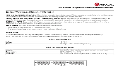
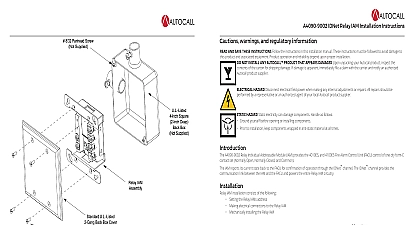
A100 5013 and A010 9935 Zone Relay Module Installation Instructions Warnings and Regulatory Information AND SAVE THESE INSTRUCTIONS Follow the instructions in this installation manual These instructions must be followed to damage to this product and associated equipment Product operation and reliability depend upon proper installation NOT INSTALL ANY AUTOCALL PRODUCT THAT APPEARS DAMAGED Upon unpacking your Autocall product the contents of the carton for shipping damage If damage is apparent immediately file a claim with the carrier notify an authorized Autocall product supplier HAZARD Disconnect electrical field power when making any internal adjustments or repairs All repairs be performed by a representative or an authorized agent of your local Autocall product supplier HAZARD Static electricity can damage components Handle as follows Ground yourself before opening or installing components Prior to installation keep components wrapped in anti static material at all times RULES AND REGULATIONS PART 15 This equipment has been tested and found to comply with the limits for a Class A device pursuant to Part 15 of the FCC Rules These limits are designed to provide reasonable protection against harmful when the equipment is operated in a commercial environment This equipment generates uses and can radiate radio energy and if not installed and used in accordance with the instruction manual may cause harmful interference to radio Operation of this equipment in a residential area is likely to cause harmful interference in which case the user will be to correct the interference at his own expense A100 5013 A010 9935 Zone Relay Module is an 8 point I O card where the I O points can be independently configured as a Class B conventional device zone a Class A conventional initiating zone using two I O points a Class B security point or a relay point This document covers the and wiring of the module information about programming the A100 5013 A010 9935 Zone Relay Module refer to ES Panel Programmer Manual 574 849AC In some cases the initiating devices on a loop require the use of the A100 5130 or A010 9916 25 V Regulator Module See the Installation sec of this document for more information 1 Compatible FACU FACU number a list of the initiating devices which are compatible with A100 5013 A010 9935 Zone Relay Module refer to 2 Wire Compatibility Chart 579 832 From this point on the A100 5013 A010 9935 Zone Relay Module card is referred to as the Zone Relay Module overview Zone Relay Module is powered in the 4100ES and 4010ES FACUs using the FACU PDI connector Some detectors may also require regulated This is done by installing the 25 V Regulator Module A100 5130 or A010 9916 in the FACU bay See 2 Wire Detector Compatibility Chart 579 832 compatibility All output zones including security zones are regulated to 25 volts when the 25 V Regulator Module is installed For jumper configuration information see the Setting the address section of this document to Figure 1 for the Zone Relay Module card layout Rev A and A010 9935 Zone Relay Module Installation Instructions 1 Front view of the Zone Relay Module card the Zone Relay Module maximum number of Zone Relay Modules that can be mounted in the 4100ES and 4010ES FACUs is limited both by the current draw of the FACU supply and the space occupied by other hardware installed in the bay mount the Zone Relay Module in the 4100ES and 4010ES FACUs complete the following steps the Zone Relay Module into an available PDI block in the bay the card with the standoffs against the back of the FACU as shown in Figure 2 the card to the standoffs using the two 6 32 screws 2 Mounting the card 2 Rev A and A010 9935 Zone Relay Module Installation Instructions the Zone Relay Module to the 25 V Regulator Module When the 25 V Regulator Module is used to power Zone Relay Modules it is dedicated to this function and cannot also be used to power wired devices older or third party detectors require a regulated voltage to operate In these cases the A100 5130 or A010 9916 25 V Regulator Module is to regulate the voltage output of the detector initiating zones For a complete list of detectors which require the 25 V Regulator Module see 2 Wire Compatibility Chart See document 579 812AC for 25 V Regulator Module mounting guidelines Up to five Zone Relay Modules can be by a single 25 V Regulator Module When the Zone Relay Module is powered by the 25 V Regulator no other connections to the regulator are permitted must order harness A100 6305 A010 6305 for each Zone Relay Module that is powered by the 25 V Regulator must mount the Zone Relay Module in the same bay as the 25 V Regulator Module connect the Zone Relay Module to a 25 V Regulator Module complete the following steps the Zone Relay Module into an available PDI block adjacent to the 25 V Regulator Module If you install more than one Zone Relay Module ensure that you wire subsequent cards in a clockwise direction without crossing the harness A100 6305 A010 6305 close to the two pin connector on the P15 mating side to expose the red and black wires See Figure 3 A clipped harness is required only for connecting the Zone Relay Module to the 25 V Regulator Module 1 4 inch 6 mm of the insulation from both 20 AWG wires carefully using a wire stripper the harness to the 25 V Regulator Module the red wire into 25V of the terminal block TB1 1 or 3 the black wire into 25C of the terminal block TB1 2 or 4 the jumpers from P14 on the card the other end of the harness to P14 on the Zone Relay Module the next card using an unmodified harness going from P15 on card one to P14 on card two step 7 to wire additional cards clockwise around the bay Use the cable tie provided to keep wires neat in the bay 3 Connected cards powered by the 25 V Regulator 3 Rev A and A010 9935 Zone Relay Module Installation Instructions and jumper configuration the address the DIP Switch SW1 to set the communications address as identified in the ES Programmer job See the Programming section of document ES Panel Programmer Manual for more information From top to bottom these switches are designated as SW1 1 through SW1 8 The of these switches are as follows SW1 1 When this switch is set to OFF the card is offline and stops communicating with the panel Set this switch to ON SW1 2 through SW1 8 These switches set the card address within the FACU Refer to Table 2 for a complete list of the switch settings for all the possible card addresses You must set these switches to the value assigned to the card by the ES Programmer SW 1 4 SW 1 5 SW 1 6 SW 1 7 SW 4 DIP switch SW1 2 4100 5103 A010 9935 card addresses SW 1 2 SW 1 3 1 4 1 5 1 6 SW 1 7 SW 1 8 point jumper configuration I O point can be configured as follows A Class B initiating device circuit IDC A Class A IDC requires two I O points in the same connector P1 P4 A Relay point normally open or normally closed A Security point Class B only I O points are configured individually and circuit types can be mixed as required configure the points do the following the jumpers as illustrated below the I O point to the desired configuration in the ES Programmer ES Programmer Manual 574 849AC 4 Rev A and A010 9935 Zone Relay Module Installation Instructions configuration relay configuration see Figure 5 and Figure 6 5 Normally open 6 Normally closed A j