Autocall Accessories A2081-9027 Circuit Protector Installation Manual

File Preview
Click below to download for free
Click below to download for free
File Data
| Name | autocall-accessories-a2081-9027-circuit-protector-installation-manual-3970125486.pdf |
|---|---|
| Type | |
| Size | 757.55 KB |
| Downloads |
Text Preview
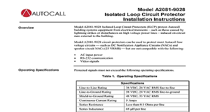
Model A2081 9027 Loop Circuit Protector Instructions Autocall Model A2081 9027 protects Autocall building system equipment from electrical transients induced on runs that are external to the building A2081 9027 will protect most Autocall low voltage circuits but is not compatible with AC input power DC power to BT FABT Transponders RS232 Communication Video Signals All signal lines which would be degraded by 6 ohms per line of added resistance Any signals which exceed the operating specifications listed below operating voltage for voltage breakdown range see chart below 27VAC RMS line to line 35VAC RMS line to ground operating current mA Resistance Ohms per line 6 Ohms per protector BREAKDOWN RANGE PER UL 497B 100V S 100V uS 70V 350V 60V 360V 110V 450V PROCEDURE See illustration on next page PER UL 497B LISTING REQUIREMENTS The external wiring must be confined to a one block area containing building of origin The wiring must also be installed in such a manner that there is no possibility of accidental by failure of supports or insulation with electric light or power conductors operating at over 300V peak to For optimum protection install the A2081 9027 apart from the protected equipment and as close as practical to point where the circuit leaves or enters the building Protected and unprotected wiring must not share the same conduit 2018 Johnson Controls All rights reserved All specifications and other information shown were current as of document revision and subject to change without notice Additional listings may be applicable contact your local Autocall product supplier for the latest status and approvals under Tyco Fire Security GmbH and the product names listed in this material are marks and or registered marks use is strictly prohibited NFPA 72 and National Fire Alarm Code are registered trademarks of the National Fire Protection NFPA 574 803AC A Mount the protector in a 4 in 10.16 cm or larger square box At least 2 in 5.08 cm distance must separate the from the conduit Cut the protector GREEN lead as short as possible and tie it to the mounting box with a standard grounding Bond the box containing the protector to the Building Grounding Electrode System Use 12 AWG 3.309 mm2 or larger solid copper wire The ground wire length must not exceed 28 ft 8.6m Bends in the ground wire of less than 2 in 5.08 cm radius are not permitted If enclosed in metal conduit the ground wire must be bonded to the conduit at both ends A Connect the protector BROWN and VIOLET leads to the lines coming from the protected equipment Connect the protector ORANGE and YELLOW leads to the lines going out of the building Connect one of the protector GRAY leads to one of the cable shields Then connect the remaining GRAY At the protector dress the input and output cables as far apart as possible no less than 2 in 5.08 cm distance At the signal source connect the cable shield to the cabinet ground screw The following represent signal to the other shield separate the two cables 2120 BMUX for communication lines Transponder or fire alarm panel for alarm initiating or signal circuits Inch Square Box Min Shield A B the Orange and Leads of ILCP Equipment A B Shield Step 6 AWG min Shield Screw AWG min Ft max Protector Ground connections the protected equipment and must be from the Grounding Electrode System 574 803AC A