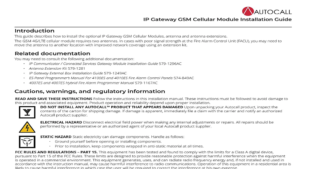
Autocall IP Gateway GSM Cellular Module Installation Guide

File Preview
Click below to download for free
Click below to download for free
File Data
| Name | autocall-ip-gateway-gsm-cellular-module-installation-guide-8945603217.pdf |
|---|---|
| Type | |
| Size | 1.93 MB |
| Downloads |
Text Preview
IP Gateway GSM Cellular Module Installation Guide guide describes how to install the optional IP Gateway GSM Cellular Modules antenna and antenna extensions GSM 4G LTE cellular module requires two antennas In cases with poor signal strength at the Fire Alarm Control Unit FACU you may need to the antenna to another location with improved network coverage using an extension kit documentation may need to consult the following additional documentation Communicator Connected Services Gateway Module Installation Guide 579 1296AC Antenna Extension Kit 579 1281 ES Panel Programmer Manual For 4100ES and 4010ES Fire Alarm Control Panels 574 849AC 4007ES and 4007ES Hybrid Fire Alarm Programmer Manual 579 1167AC Gateway External Box Installation Guide 579 1249AC warnings and regulatory information AND SAVE THESE INSTRUCTIONS Follow the instructions in this installation manual These instructions must be followed to avoid damage to product and associated equipment Product operation and reliability depend upon proper installation NOT INSTALL ANY AUTOCALL PRODUCT THAT APPEARS DAMAGED Upon unpacking your Autocall product inspect the of the carton for shipping damage If damage is apparent immediately file a claim with the carrier and notify an authorized product supplier HAZARD Disconnect electrical field power when making any internal adjustments or repairs All repairs should be by a representative or an authorized agent of your local Autocall product supplier HAZARD Static electricity can damage components Handle as follows Ground yourself before opening or installing components Prior to installation keep components wrapped in anti static material at all times RULES AND REGULATIONS PART 15 This equipment has been tested and found to comply with the limits for a Class A digital device to Part 15 of the FCC Rules These limits are designed to provide reasonable protection against harmful interference when the equipment operated in a commercial environment This equipment generates uses and can radiate radio frequency energy and if not installed and used in with the instruction manual may cause harmful interference to radio communications Operation of this equipment in a residential area is to cause harmful interference in which case the user will be required to correct the interference at his own expense information CANADA INTERFERENCE STATEMENT device complies with Part 15 of the FCC Rules and ISED Canada licence exempt RSS standard s Operation is subject to the following two 1 this device may not cause interference and 2 this device must accept any interference including interference that may cause operation of the device pr appareil est conforme aux CNR d ISED Canada applicables aux appareils radio exempts de licence L exploitation est autoris aux deux suivantes 1 l appareil ne doit pas produire de brouillage et 2 l utilisateur de l appareil doit accepter tout brouillage radio subi si le brouillage est susceptible d en compromettre le fonctionnement CLASS A DIGITAL DEVICE NOTICE equipment has been tested and found to comply with the limits for a Class A digital device pursuant to part 15 of the FCC Rules These limits are to provide reasonable protection against harmful interference in a residential installation This equipment generates uses and can radiate frequency energy and if not installed and used in accordance with the instructions may cause harmful interference to radio communications there is no guarantee that interference will not occur in a particular installation If this equipment does cause harmful interference to radio television reception which can be determined by turning the equipment off and on the user is encouraged to try to correct the interference by one more of the following measures the separation between the equipment and receiver Reorient the receiving antenna Connect the equipment into an outlet on a circuit different from that to which the receiver is connected Consult the dealer or experienced radio television technician for help ICES 3 B NMB 3 B Rev D Gateway GSM Cellular Module Installation Guide CANADA WIRELESS NOTICE equipment complies with FCC and ISED Canada radiation exposure limits set forth for an uncontrolled environment The antenna should be and operated with minimum distance of 20 m between the radiator and your body The antenna used for this transmitter must not be co or operating in conjunction with any other antenna or transmitter except as described in this user manual appareil est conforme aux limites d exposition aux rayonnements de la IC pour un environnement on contr L antenne doit install de fa garder une distance minimale de 20 centim entre la source de rayonnements et votre corps L antenne utilis pour cet ne doit pas situ ou op en conjonction avec une autre antenne ou sauf tel que d dans ce mode d emploi gain must be below Gain de l antenne doit ci dessous 1 Antenna gain reference band A010 6416 A007 6416 A010 6417 A007 6417 dBi dBi dBi dBi dBi dBi dBi B5 UL 824 849 DL 869 894 UL 1850 1910 DL 1930 1990 B12 UL 699 716 DL 729 746 UL 777 787 DL 746 756 UL 824 849 DL 869 894 UL 1710 1755 DL 2110 2170 UL 1850 1910 DL 1930 1990 To satisfy FCC RF exposure requirements for mobile transmitting devices a separation distance of 20 cm or more must be maintained the antenna of this device and persons during device operation LABEL modular transmitter LE9080 is labeled with its own FCC ID and IC number When the module is installed inside the host device and the FCC ID of the module is not visible the host device displays the provided label referring to the FCC ID and IC of the enclosed module This label is shipped with the module and it is the responsibility of the integrator to apply it to the exterior of the enclosure as displayed in the following figure modulaire LE9080 est avec son propre ID FCC et le num IC Lorsque le module est install l int du dispositif h et la ID IC du module ne soit pas visible le dispositif d accueil affiche l fournie se r l ID FCC et IC du module ci joint Ce label est livr le module et il est de la responsabilit de l int de l appliquer l ext de l enceinte comme indiqu dans la figure suivante LE9080 FCC ID F5318LE9080 IC 160A LE9080 1 Label placement 2 579 1248AC Rev D IP Gateway Cellular Module is an optional module used with the IP Gateway Modules The cellular module connects the IP Gateway to a cellular Gateway GSM Cellular Module Installation Guide GSM 4G LTE cellular modules include two antennas See Table 2 for a list of PIDs the case of poor signal strength at the FACU you may require an optional antenna extension kit See Table 3 for compatible extension kit 2 IP Gateway Cellular Module 2 Cellular module PIDs module kit description 4G LTE module kit PIDs for IP Gateways mounted the FACU module kit PIDs for IP Gateways mounted an external box 3 Antenna extension kit PIDs kit feet 4.57 m antenna extension kit feet 7.62 m antenna extension kit feet 15.24 m antenna extension kit extension kit PIDs IP Gateway Cellular Module attaches to the IP Gateway which may come pre installed in new FACUs Table 4 for cellular module electrical requirements and for environmental limitations 4 Electrical and environmental specifications specifications DC 24 V draw through the IP mA V battery from SPES see note DC specifications When the SPES powers the IP Gateway add the current draw of the cellular module to the current draw of the IP Gateway and calculate the 24 battery draw using the SPES current draw table in the Specifications section of Power over Ethernet Switch Module Installation Guide 579 1250AC operation with ambient temperature outside the cabinet at 32 to 120.2 0 to 49 operation under non condensing humi

