Cornell Communications 4200 Detailed Operation Instructions

File Preview
Click below to download for free
Click below to download for free
File Data
| Name | cornell-communications-4200-detailed-operation-instructions-9874630125.pdf |
|---|---|
| Type | |
| Size | 655.76 KB |
| Downloads |
Text Preview
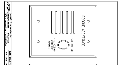
Rescue Assistance 4200 Instructions GENERAL following information provides an overview of the features that are designed into the standard components of the system Annunciators are available in a variety of sizes between 4 and 44 Zones Each such Annunciator is as A 42NN where NN Zone Capacity between and in multiples of four SERIES ANNUNCIATOR 4200 Series Annunciator incorporates the following features Green On LED Indicates that Annunciator is receiving DC Power from the Power Supply Normal On Push To Talk P T T Switch For initiating Out Going Audio to the selected Call Station Reset Switch to Reset the system once all calls have been answered processed labeled ALL ZONES Microphone For Out Going Talk Intercom functions Speaker for audible tone indication and for In Coming Listen Intercom functions Zone Control and Indication The following are duplicated for each Zone Yellow Fault LED for visual indication of Fault Status Zone Control Switch Used to Acknowledge Answer Calls from the corresponding Call Station Red Call LED For visual indication of Call Status for the corresponding Call Station Green On LED For visual indication of Audio connections CALL STATION Call Stations consist of the following Model 4201B VM 4201B V 4201B 4201A Newest to Oldest Such Call Station incorporates the following features Call Switch for placement of calls from the station Mushroom Head Round Metal or Square Plastic Call Status LED Lamp built into or mounted separately above it Duplicates Red LED at Annunciator Speaker for Tone and Intercom functions Supplies that are used for 4200 Series Systems usually consist of Cornell B 5243 Series units These Power require a hard wired connection to a 120 VAC Primary Power Source which they convert to DC Power for by the 4200 System SUPPLY S Models A 4204 thru A 4224 typically require 1 Poower Supply configured to provide 24 Volts DC Models A 4228 thry A 4244 typically require 2 Power Supplies Configured for Output 24 Volts DC Configured for Output 12 Volts DC to for more information 3 2010 1 of 7 OPERATION B1 thru B5 below explain how a 4200 Series Rescue Assistance System normally functions and the process by which Calls are normally handled NORMAL STATUS a Cornell 4200 Series Rescue Assistance System is in the normal Stand By state the following will be observed At each 4201 Call Station Silent LED Lamp not illuminated At the 42XX Annunciator Audible Indication Silent Only the following Visual Indication should be evident Green ON LED Illuminated Steady depress the call button on the Call Station This will trigger the following actions A CALL FROM A 4201 CALL STATION At the 4201 Call Station At the 42XX Annunciator Audible Indication Visual Indication The Red Call Status LED illuminates Steady A short acknowledge tone will be produced Red LED built into corresponding Zone Switch illuminates Steady Slow Repeating Beep Tone sounds as long as non acknowledged calls exist ACKNOWLEDGING A CALL FROM THE A 42XX ANNUNCIATOR Acknowledge the Call press the corresponding Zone Control Switch When this is done the following occurs At the Station Acknowledgement of the call is indicated via the Red Call Status LED changes from Steady to Flashing At the 42XX Annunciator the following actions occur for the corresponding Acknowledged Station Zone The Red Call Status LED changes from Steady to Flashing The Green On LED for the corresponding Zone illuminates Steady A Audio Path is established between the Annunciator and the Acknowledged Station should be able to hear any activity occurring in the vicinity of the selected Call Station The repeating Beep tone at the Annunciator will stop if there are no other un acknowledged calls USING THE INTERCOM FUNCTIONS FROM THE A 42XX ANNUNCIATOR the person who placed the Assistance Call is capable of conversing via intercom no further action is required on their part If you not already established an Audio Connection by pressing the corresponding Zone Control Switch do so for the desired Call This is the same as Step above Once you do observe the following At the Station the Call Station Speaker is used both as a Speaker and as a Microphone The Intercom Operation provided by the 4200 Area of Rescue System is Half Duplex it only works in one direction at a time must switch between and Modes The default mode is In Coming Listen At the 42XX Annunciator To Talk to the selected Call Station Press the switch and hold it while you are Release it to listen to any reply from the selected Call Station RE SETTING THE 4200 SYSTEM TO NORMAL STAND BY MODE A 42XX Annunciator incorporates circuitry to prevents the system from being Reset if any Non Acknowledged Calls exist it is important to note that ALL active calls MUST be Acknowledged see Step above prior to any attempt to Reset Annunciator all active calls have been acknowledged ALL active Red LEDs should be flashing NO Green Zone LEDs should be lit press and release the ALL ZONES switch you will need to flip up the spring loaded clear cap Once this done the system should return to the Normal Stand By Mode see Step above 3 2010 2 of 7 OPERATION 4200 Area of Rescue Assistance System incorporates features that are intended to continuously monitor the connections the Annunciator and each of the Call Stations The following informat ENABLING AND DISABLING FAULT DETECTION each A 42XX Annunciator Configuration Jumpers are provided with one such jumper provided per each Zone These are intended to disable fault detection for Zones that are not used Operation of these Jumpers is as follows A Call Station will be connected to the Zone Fault Detection Enabled in position in Used position Field wiring will not be connected to the Zone Fault Detection Disabled WHEN LINE FAULTS ARE DETECTED a Call Station and or the associated wiring fails or becomes disconnected or disarranged a FAULT status condition be reported at the A 42XX Annunciator as follows The Yellow Fault LED corresponding to the affected Zone Station will illuminate in a steady manner and will remain until the Fault condition is corrected The Annunciator Panel Speaker will produce a continuous Beep Tone at regular intervals until the Fault condition is corrected TROUBLESHOOTING HINTS SUGGESTIONS problems occur or when the 4200 System fails to operate as previously described some sort of failure may exist may have Although it is not practical to describe all such failures and their solutions the following topics may assist you in and or fixing common problems that have occurred in the past QUICK CHECKLIST proceeding with any other troubleshooting Cornell suggests that you proceed with the following checklist which will many common installation problems This list is also highly recommended as a Pre Installation Checklist Obtain a set of the latest 4200 Installation Wiring Diagrams The latest drawings include important information about types terminations and other important precautions In order to properly troubleshoot a 4200 Series System you will likely need a set of these drawings They can be obtained from the Cornell website www cornell com Visual Inspection Particularly recommended for Pre Installation If you have not already done so remove the Annunciator from the back box and conduct a brief inspection In particular look for metal objects which may have vibrated loose shipment in operation and may have lodged between the circuit bo


