Cornell Communications Control Unit Visual Only 128 station HTN7680UA

File Preview
Click below to download for free
Click below to download for free
File Data
| Name | cornell-communications-control-unit-visual-only-128-station-htn7680ua-9032548167.pdf |
|---|---|
| Type | |
| Size | 694.43 KB |
| Downloads |
Text Preview
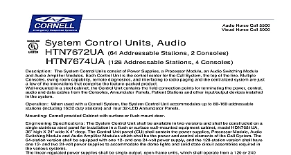
Visual Nurse Call 5000 Contol Unit Visual Only The Special System Control Unit is designed with Assisted Living facilities in mind It a Processor Module which will accommodate up to 128 addressable stations and Power Four Annunciator Panels multiple consoles swing room capability remote diagnostics interfaces to printer and radio page systems are just a few of the innovations that comprise the product With this Special Control Unit nurse consoles may be used as an easy of entering pocket paging assignments mounted in a steel cabinet the Control Unit contains the field connection points for terminating power control and data cables from the Staff Consoles Annunciator Panels Patient Stations other input output devices installed in the system When used with a Cornell System the System Control Unit accommodates up to 128 stations 32 Duty Status and four 32 LED Annunciator Panels Cornell provided cabinet with Flush or Surface Mounted door Specifications The Control Unit shall be a wall mounted control panel model 128 station The panel shall be mounted in an electrical equipment cabinet model 24 constructed of 14 gauge steel and equipped with one of two types lockable doors flush HDN7682UA or surface HDN7683UA The cabinet shall be equipped with cutout for a standard duplex receptacle for plugging in the power supply line cords inside the The Control Unit shall supply power and control voltages and the field termination points to install and operate the Staff Call System The Control Unit shall include a serial data to communicate from one Console to another monitor system status activate selected change room map parameters perform system diagnostics etc The RS 232 serial data for interface to a radio paging system a modem or to a standard video terminal device used to room map parameters and perform system diagnostics The Control Unit shall be equipped a separate Common Equipment Ground terminal clearly identified as such to be used by the to terminate all designated Equipment Grounding conductors wire color GREEN or w YELLOW stripe Information Power Requirements The Control Unit power supplies shall be all solid state and proved VDC for dome light power and 12 VDC for control and logic circuits in the system power supply shall be adequately protected from overload and short circuits Operating Environment 50 120 Indoor Non condensing Physical Dimensions 24 x 36 x 4 Mounting Provided Cabinet Wiring 22 AWG Minimum


