DSC CFP 102 v1 0 IM EN NA

File Preview
Click below to download for free
Click below to download for free
File Data
| Name | dsc-cfp-102-v1-0-im-en-na-1457629830.pdf |
|---|---|
| Type | |
| Size | 1.25 MB |
| Downloads |
Text Preview
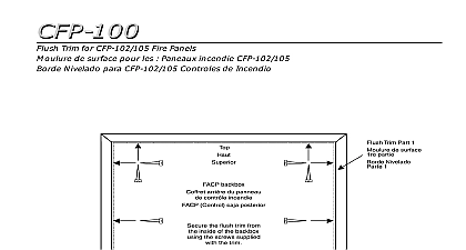
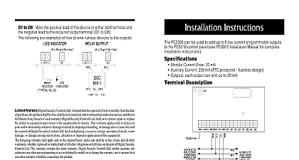
CFP 102 Alarm Control Panel 1.0 This manual contains information on limitations regarding use and function and information on the limitations as to liability the manufacturer The entire manual should be carefully read of Contents Section 1 Introduction 1 The CFP 102 Fire Alarm Control Unit 1 Codes Standards and Installation Requirements 1 Technical Support and General Information 2 Section 2 Preparing to Install the CFP 102 Fire Panel 3 Unpacking the CFP 102 3 CFP 102 Overview 3 Planning Your Installation 4 Electrical Specifications 4 Panel Current Ratings 5 Standby Battery calculation chart 5 Calculation for Standby Battery Requirement 6 Section 3 Installing the CFP 102 Fire Panel 7 Finding a Place to Mount the CFP 102 7 Panel Assembly 7 Mounting 8 Section 4 Wiring the CFP 102 9 Wiring Specifications 9 Section 5 Panel Operation 12 Operating Sequences 12 General Zone Fire Alarms 12 Waterflow Alarms 12 Supervisory Zone Alarms 13 Trouble Operation 13 System Reset Operation 14 Lamp Test 14 Walk Test Installer function only 14 NAC operation 15 Relay Function 15 Section 6 Programming the CFP 102 System 16 How to Program the CFP 102 16 Programming Section Descriptions 17 Viewing the Event Buffer 22 Section 7 Startup of the CFP 102 23 Prior to power up 23 Power up sequence 23 Default Operation 23 Programming the Panel 23 Final Verification 23 Section 8 Programming Worksheets 24 Entering Programming Mode 24 Zone Programming Section 0 24 NAC Temporal Steady Programming Section 1 25 NAC Auto silence Strobe Programming Section 2 25 Silence Inhibit and Walk Test Programming 3 25 Waterflow Programming Section 4 25 Auto Verify Programming Section 5 26 Section 9 Warranty and Warning Information 27 Warning 27 Limited Warranty 29 The CFP 102 Alarm Unit Codes Standards Installation Section 1 Introduction General features initiating device circuits class B style B notification appliance circuits class B style Y Power Limited be wired as one NAC class A style Z One common alarm actuated relay form One common trouble actuated relay form Unswitched common and switched common auxiliary power returns battery charger with dead front construction mounted in the cabinet power output 500 mA max Power Limited Applications CFP 102 two zone fire alarm control panel is listed for use in the following applications Premises Fire Alarm System for the following types of service automatic M Manual SS Sprinkler Supervisory WF Waterflow Relevant codes and standards CFP 102 fire alarm control panel is designed to meet the requirements of NFPA 72 1996 UL 864 Control Units for Fire Protective Systems 1996 edition and in Canada CAN Standard for Control Units for Fire Alarm Systems 1999 edition provided with this unit is intended as a guide Installation of this equipment system components alarm initiating devices and notification appliances must follow manufacturer guidelines as contained in their respective installation documents all appli codes and the instructions of the Local Authority Having Jurisdiction General Installation requirements documents installing the CFP 102 control panel refer to this manual When installing optional sys components refer to the installation documents included with those components When compatible alarm initiating devices or notification appliances refer to the installation included with those products wiring wiring recommendations in this document are intended as guidelines All field wiring be installed in accordance with NFPA 70 National Electrical Code and in Canada with standard for installation ULC S 524 the most current Canadian Electrical Code with all local codes and standards and the Authority Having Jurisdiction devices UL or ULC Listed smoke detectors and notification appliances that are compatible with CFP 102 Fire alarm control panel from the lists included in this manual detector alarm verification CFP 102 alarm initiating zones can be configured for Verification If this feature is then do not use smoke detectors with built in Alarm Verification Use of alarm verification may require the approval of the local AHJ Technical and technical support from DSC Call toll free 1 800 387 3630 Canada US general product information visit the DSC web site www dsc com System Verification complete fire alarm system must be verified for proper installation and operation when initial installation is ready for inspection by the Local Authority Having Jurisdiction system component is added changed or deleted programming changes are made wiring has been altered or repaired failure due to external influences such as lightning water damage or extended outages has occurred Standby Power CFP 102 provides standby battery support for lead acid rechargeable batteries The capacity of the standby batteries must be calculated using the charts and tables this manual for the period as required by national or local codes and standards Even the calculation table within this manual includes a safety margin lead acid batteries used for standby can have variable capacity as a result of age and ambient Periodic inspection for damage and the batteries ability to support the attached is highly recommended Unpacking the Section 2 Preparing to Install CFP 102 Fire Panel basic CFP 102 package includes the following components with hinged door and control plate c w display and control printed circuit board label insert compartment dead front plate control PCB manual pack 2 NAC EOL resistors 4.7 K 5 W 5 Zone EOL resistors 4.7 K 5 W 1 Battery jumper wire 1 EGND terminal ring 1 EGND KEP nut keys taped to outside of cabinet components described above are factory assembled into the enclosure Accessories Number plate resistor for NAC and Initiating circuits in the field gang plate with EOL resistor Mounts to a single electrical backbox CFP 102 cabinet with door closed display and controls Planning Your Zone Label Insert zone label insert is installed in the zone window area behind the display control panel and remove the insert Zone designations can be