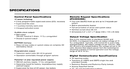
DSC PC1550 v4 0 - Installation Manual - English - ClassicSeries 6 Zone Alarm Control Panel

File Preview
Click below to download for free
Click below to download for free
File Data
| Name | dsc-pc1550-v4-0-installation-manual-english-classicseries-6-zone-alarm-control-panel-1068743952.pdf |
|---|---|
| Type | |
| Size | 953.90 KB |
| Downloads |
Text Preview
TABLE OF CONTENTS the Panel 3 the Keypad 3 Power Connection 3 Terminal Connections 3 Connection 3 Wiring 3 Zone Wiring 3 Zone Wiring 3 Connection 3 Line Wiring 3 FOR LOCATING SMOKE DETECTORS 4 FUNCTIONS 5 Code 5 Master Code 5 Programming Code 5 5 Arming 5 Without Entry Delay 5 5 Bypassing Q 1 5 Conditions Q 2 5 Memory Q 3 6 Callup Command Q 4 6 Programming Commands Q 5 6 Reset 6 Function Commands Q 6 Master Code 6 Output Command or Q 7 Access Code 7 Programming Command Code 7 without Entry Delay Q 9 Access Code 7 For The Night Q 1 7 Command Q 0 when armed 7 Command Q 0 7 Zones 7 to Program 8 Data Review 8 Data Display 8 Data Programming 8 Sections 8 Binary Programming 8 1st Phone Number 8 1st Account Code 8 2nd Phone Number 9 2nd Account Code 9 to 10 Reporting Codes 9 Zone Alarm Reporting Codes 9 Zone Restoral Reporting Codes 9 Closing Arming Reporting Codes Closing Reporting Code 9 Opening Disarming Reporting Codes Alarm Reporting Code 9 Priority Alarms and Restorals 9 Maintenance Alarms and Restorals 10 Zone Definitions 10 1st System Option Code 11 2nd System Option Code 11 3rd System Option Code 11 Communication Variables 11 Zone Bypass Mask 11 System Times 11 Auxiliary Delay Loop Entry Exit Times 12 System Clock Times 12 New Installer Code 12 New Master Code 12 2nd Master Code 12 Communication Formats 12 Programmable Output Options PGM Terminal 13 Communicator Call Directions 13 Downloading Telephone Number 13 Downloading Access Code 13 Panel Identification Code 13 Number of Rings Before Answering 13 Reset to Factory Default 13 4th System Option Code 14 5th System Option Code 14 Answering Machine Double Call Timer 14 6th System Option Code 14 LINKS1000 Test Reporting Code 14 Keypad Lockout Control 14 Installer Lockout Enable 14 Installer Lockout Disable 14 THE RECORD WORK SHEETS WARRANTY front cover CANADA NOTICE front cover PANEL WIRING DIAGRAM inside back cover Control Panel Six fully programmable zones EOL resistor supervised option all zones programmable as fire zones maximum zone loop resistance 100 ohms Bell Siren outputs 1 amp steady for burglary pulsed for fire Programmable output 300 mA programmable options Auxiliary power output 475 mA PC1500RK keypad 3 maximum Sealed Battery 12 VDC 4 Ah minimum Transformer 16 VAC 40 VA Panel dimensions 10 high x 8 wide x 3 deep 254 x 208 x 76 mm Surface mount Panel colour light beige Keypad Three keypad activated zones Auxiliary Panic Backlit keys 5 system lights 6 zone lights Keypad dimensions Armed Memory Bypass Trouble 4.5 H 4.5 W 0.93 D 114 114 23.6 mm Surface mount Keypad colour mist Programmable PC1550 is complete with a default program so that it is with a minimum of programming The control panel is programmable from the keypad Memory panel uses EEPROM memory which will retain all program even if AC and battery power are removed from the The EEPROM memory can be reprogrammed thousands of Protection PC1550 has been carefully designed and tested to provide protection against static and lightning induced transients special circuit board design catches high voltage right at the wiring terminals and transient protection are placed in all critical areas to further reduce damaging Low or disconnected battery Loss of AC power Fuse open Loss of time on system clock Microprocessor circuit Download Upload capability Programmable auto downloading Swinger shutdown Transmission delay Six access codes key code All zones programmable as fire zones Programmable test transmission Zone bypass from the keypad Six zones Bell Siren zone Programmable output Three dedicated keys Fire Auxiliary Panic Backlit aesthetically pleasing keypad the Panel a dry location close to an unswitched AC source and close the telephone line connection Remove the printed circuit board mounting hardware and the keypad from the cardboard retainer the cabinet Before attaching the cabinet to the wall press four white nylon printed circuit board mounting studs into the from the back Once the cabinet is mounted to the wall pull the cables into the cabinet and prepare them for connection Use meter to test the wiring for opens shorts and grounds Press the board onto the white nylon mounting studs Complete all to the control panel before applying AC power


