Edwards 116EXMLED Installation Sheet

File Preview
Click below to download for free
Click below to download for free
File Data
| Name | edwards-116exmled-installation-sheet-1902835764.pdf |
|---|---|
| Type | |
| Size | 989.93 KB |
| Downloads |
Text Preview
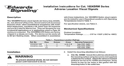
Installation Instructions for 116EXMLED Series LED Lights for Use in Hazardous 116EX S 116EX C CONDUIT 116EX P CONDUIT WALL MOUNTED CONDUIT 116EX B HUB 1 4 CONDUIT SERIES HOUSING AND GLOBE WITH GUARD 1 Mounting Options 116EXMLED Series AdaptaBeacon LED signaling appliances intended for general utility signaling use When assembled an available mounting subassembly 116EX P 116EX C or 116EX C with 116EX B and in accordance with instructions the 116EXM LED visual signal is UL Listed as Visual Signal Appliance The 116EXMLED is UL and cUL listed use in Class I Division 1 Groups C and D Class I Division 2 A B C and D Class II Division 1 Groups E F and G II Division 2 Groups F and G and Class III Division 1 and hazardous locations with operating temperature codes per 2 beacons are UL and cUL Listed for outdoor use with 3R 4X and Marine rated enclosures LED beacon flashes a 360 degree beam of light with 14 user flash patterns LED beacons are available in pendant bracket ceiling or mount models Figure 1 reduce the risks of ignition of hazardous and shock do not apply power to unit until installation has been completed unit is tightly assembled and secured this unit in accordance with the applicable requirements the latest edition of the National Electrical Code and Canadian Code Mount using the following applicable method Pendant Mount Models Figure 2 Install the catalog 116EX P pendant mounting module to the housing tighten set screw Install explosion proof box not supplied Secure 3 4 19 mm NPT conduit not supplied to the box Install the on the conduit Ensure conduit engages at least full threads and then tighten the set screw to secure pendant mount module to the conduit Make connections in accordance with Figure XX to Table 2 for required supply wire temperature Ceiling Mount Models Figure 3 Install the catalog 116EX C ceiling wall mounting module using hardware not supplied suitable for the surface Make electrical connections in with Figure 6 Refer to Table 2 for required wire temperature ratings Install main housing ceiling mount module Tighten the set screw to the 116EXMLED main housing to the ceiling module Bracket Mount Models Figure 4 Install the catalog 116EX C ceiling wall mounting module using hardware not supplied for the mounting Connect field earth ground wire to ground or earth ground via conduit system Install catalog number 116EX B wall mounting elbow to 116EXMLED main housing feed the units wiring the 116EX B elbow Tighten the set screw to the 116EX B elbow to the main housing Make connections in accordance with Figure 6 to Table 2 for required supply wire temperature Install main housing and 116EX B elbow to ceiling mount module Tighten the to secure the 116EX B elbow to the ceiling module Stanchion Mount Models Figure 5 Install the catalog 116EX S stanchion mount module to the main and tighten set screw Mount the 116EX S to 1 1 4 conduit tighten set screw Ensure conduit connected to the appropriate junction box Install unit on the conduit Make electrical connections in with Figure 6 Refer to Table 2 for required wire temperature ratings CT 800 336 4206 FAX 800 454 2363 3101456 ISSUE 1 2008 Screw s 3 4 1 4 3 4 1 4 3 4 2 Detail of Pendant Mounting 3 Detail of Ceiling Mounting Adjust flash rate Beacons are factory defaulted to mode 3 65 flashes per minute Remove globe section loosen the globe and ring set screw Insert a suitable tool into the in the globe and ring assembly and loosen the by prying in a counterclockwise direction the ring and globe assembly Set dipswitch Figure 7 for desired flash rate Refer Table 3 for dipswitch settings To replace simply screw the globe assembly unit until it seats firmly onto its gasket Tighten the unit 1 8 to 1 4 turn Tighten the set screw reduce the risk of ignition of hazardous and shock keep assembly tightly when circuits are energized reduce the risk of ignition of hazardous and shock disconnect from the and circuit and allow five 5 minutes for energy to dissipate before disassembling unit Apply power to the unit and ensure proper function reduce the risk of ignition of hazardous and shock keep assembly tightly when circuits are energized the unit as follows Figure 8 Loosen the 3 guard screws and remove the guard Loosen the globe and ring assembly set screw Insert a tool into the notches in the globe and ring assembly loosen the assembly by prying in a counterclockwise Remove the ring and globe assembly Refer to Table 1 for the correct replacement catalog number replace the necessary part To replace simply screw the unit on until it seats firmly onto gasket Tighten the unit another 1 8 to 1 4 turn Tighten setscrew Reinstall the guard where applicable and secure using the supplied screws functions properly After the unit is assembled apply power and make sure the 3101456 ISSUE 1 2 9 16 7 16 3 4 1 16 13 16 Screws 1 4 1 4 3 4 1 2 1 4 4 Detail of Wall Bracket Mounting 5 Detail of Stanchion Mounting field earth ground wire to ground screw or ground via conduit system wire nuts connect unit two white wires to neutral AC or incoming DC wire nuts connect unit two black wires to hot AC or incoming DC 6 Wiring Bracket Mount Version Shown MODE MODE Source Guard 7 Detail of Dipswitch Location 8 Disassembly of the 116EXMLED Series 3101456 ISSUE 1 3 120 240V 50 60 Hz 215A DC 176A 1 116 Series AdaptaBeacons NPT NPT 1 4 NPT Less Module Module Module Module Bracket Elbow in this position denotes color of the lens A amber B blue W clear G green R red 2 Ratings Temperature Wire Marking I Div 2 A B 135 160 160 I Div 1 2 II III Div 1 II III Div 2 C D 85 85 85 E F G 120 135 135 F G 120 135 135 3 Flash Mode Selection OFF OFF OFF OFF OFF OFF ON OFF ON OFF OFF OFF ON ON OFF OFF OFF ON ON OFF OFF OFF 1 2 3 4 1 2 3 4 5 6 7 8 On Bursts Delay Repeat Bursts Delay Repeat Bursts 3 Bursts Repeat Bursts delay w slight illumination Repeat FPM 10 Duty Cycle FPM 25 Duty Clyle FPM 50 Duty Clyle FPM 75 Duty Clyle FPM 10 Duty Clyle FPM 25 Duty Clyle FPM 50 Duty Clyle FPM 75 Duty Clyle up and then ramps down Edwards 3101456 ISSUE 1 336 4206