Edwards ANS Amplifiers Install

File Preview
Click below to download for free
Click below to download for free
File Data
| Name | edwards-ans-amplifiers-install-3681950742.pdf |
|---|---|
| Type | |
| Size | 860.66 KB |
| Downloads |
Text Preview
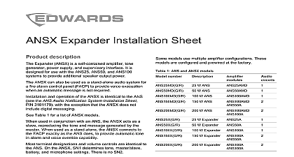
Audio Notification System Installation Sheet description Audio Notification System ANS is a self contained tone generator digital message repeater and interface It is designed for use with a UL Listed alarm control panel FACP to provide a listed voice alarm system See Table 1 for a list of ANS FACP provides all initiating circuitry and a notification circuit NAC that connects to the ANS The ANS its own internal supervision and supervision for its lines The ANS reports faults to the FACP by placing open on the FACP NAC Optionally faults can be reported the FACP by connecting a supervisory circuit to the ANS ANS reports internal failures and speaker line faults by an open on the supervisory circuit models of the ANS are powered by a 120 V 60 Hz supply the ANS can be powered by 24 Vdc from a UL Listed alarm power supply Each model provides a different power but all models can be configured for 25 or 70 Vrms by jumper The factory setting is for 25 Vrms models model numbers have the format ANS999MDC Each is a complete audio notification panel including a built in generator power transformer and cabinet The 999 represents the output power 25 50 100 150 or watts M indicates the inclusion of a microphone D the inclusion of a digital message repeater DMR C the cabinet color either gray G or red R model numbers have the format ANS999XC Each is a complete expander panel including a built in tone power transformer and cabinet The 999 portion the output power X indicates an expander module have no microphone and no DMR C indicates the color either gray G or red R model numbers have the format AMS999AMD The include a built in tone generator but no transformer cabinet The 999 portion represents the power output The A indicates an amplifier M indicates the inclusion of microphone D indicates the inclusion of a digital message Expander can operate as a slave amplifier when connected an ANS999AMD which supplies source audio to the slave can also operate as stand alone audio notification with only tone and microphone amplification models use multiple amplifier configurations These are configured and prewired at the factory 1 ANS models number W ANS W ANS W ANS W ANS W ANS W Expander W Expander W Expander ANS100A W Expander ANS100A W Expander ANS100A 2 Specifications voltage current 120 Vac current battery A with load A A A power voltage 24 Vdc input 1 A A A Vac at 60 Hz or 24 Vdc A A A A A A A A A A A A A A W to 2800 Hz 400 to 4000 Hz 400 to 4000 Hz W W or 70 Vrms selectable open and short circuit protected 2013 UTC Fire Security All rights reserved 12 3101179 REV 03 REB 28FEB13 charging capacity 2 NAC current V 18 Ah V 24 Ah V 7 Ah V 18 Ah mA maximum Input current measurements are determined using test conditions in UL 1711 Sine represents measurements made while the produces a continuous undistorted sine wave of 1 kHz into the load of 25 50 or 100 W at the rated output voltage Alarm is the current the unit experiences delivering an alarm signal whoop to the rated load Standby is the current draw of the with all normal power on and auxiliary terminals fully loaded standby is the current draw from the batteries on loss of power an otherwise normal standby state All ANS cabinets hold two 12 V 7 Ah batteries Larger batteries an external battery cabinet instructions that all wiring and devices installed in the system meet following standards NFPA 70 National Electrical Code NFPA 72 National Fire Alarm and Signaling Code NFPA 101 Life Safety Code this equipment in a clean dry environment Avoid where the equipment could be subjected to Remove all electronic assemblies from the enclosure drilling or punching the enclosure Where possible all cable entries from the rear or sides Before making modifications to the enclosure be certain that they will not with the assemblies or batteries state and local codes instructions to Figure 1 for terminal designations and to diagrams in section for wiring diagrams Connect the speaker lines to TB1 5 and TB1 6 sure to observe polarity and connect all speakers using same polarity For Class A Style Z the returns are and TB1 8 When using 70 VRMS speakers the speaker wiring be enclosed in grounded metal conduit Connect the microphone to connector P2 the microphone is not installed ensure that switch is in the OFF position Attach the appropriate EOLR for the FACP to TB3 3 and 4 for the speaker circuit to TB3 5 and 6 must use EOLR value specified for the FACP appliance circuit NAC See the FACP instructions provided by the manufacturer if your system includes one or more ANSZS4B zone the FACP EOLR must be relocated See the installation sheet P N 3101185 Connect the FACP signaling circuit to TB1 3 and using the FACP alarm polarity Connect the mains power 120 Vac at 60 Hz to the black white pigtail leads from transformer primary Secure ground lead to the grounding stud in the cabinet Connect the battery wiring harness Red and Black the correct polarity two 12 V batteries connected in series See 4 If the unit does not have its own batteries and on an external power supply with battery backup that switch SN2 7 is in the OFF position Wiring for batteries is nonpower limited Maintain a spacing of 1 4 in between power limited wiring nonpower limited wiring the batteries must be located in a separate enclosure a separate conduit run for the battery wiring only When all power and circuits are connected the green LED on and stays on to indicate that the ANS is fully and all circuits are normal designations to Figure 1 for the locations of the terminals 3 Terminal descriptions 2 4 input 24 to 32 Vac Vdc 1 4 NAC input 10 mA max Alarm polarity is shown loop Style Y Z Class A B start 2 4 loop Style Z Class A return 2 4 negative audio input 0.5 Vrms nominal 1 Vrms 1 mA max in out 600 0 dBm 1 3 5 Programmable output 1 3 5 active 1 3 5 audio enable 24 Vdc 32 Vdc 5 mA max 1 3 signal activate 24 Vdc 32 Vdc 5 mA max 1 3 voltage 24 Vdc 0.1 A when unit is in alarm 2 3 5 V 24 Vdc 0.1 A Disconnected in alarm 2 3 24 Vdc 0.1 A 2 3 PTT 24 Vdc 0.1 A 5 FACP supervisory circuit See installation for details 32 Vdc 0.4 A max Must be using J1 1 4 Signal Supervisory circuit EOLR 6 8 2 4 12 3101179 REV 03 REB 28FEB13 GAIN and MIC GAIN MSG GAIN message gain and MIC GAIN microphone potentiometers are factory set and should only be by trained technicians with the proper test equipment increase the output of a speaker change the speaker tap or setting to a higher wattage S1 switch S1 performs a hard reset of the ANS This is not required during normal operation should only be done at the request of our support switch settings settings to Figure 1 for DIP switch locations The following table the factory settings and descriptions for the switches 4 Factory D