Edwards ANSREM Remote Mic Install

File Preview
Click below to download for free
Click below to download for free
File Data
| Name | edwards-ansrem-remote-mic-install-1359760482.pdf |
|---|---|
| Type | |
| Size | 708.08 KB |
| Downloads |
Text Preview
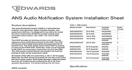
Remote Microphone Installation Sheet description ANSREM is a supervised remote microphone panel for with the ANS25 ANS50 and ANS100 audio notification The ANSREM makes it possible to send emergency messages through the system speakers from a location is remote from the ANS panel ANSREM uses 3 pair shielded cable to connect to supervisory card which is mounted within the master panel Fault conditions in the wiring or in the microphone circuitry are reported to the fire alarm panel FACP using the same supervisory path as the master panel 1 Specifications voltage current Vdc mA mA to 22 AWG Vdc mA mA to 22 AWG the system is in the alarm state keying the ANSREM interrupts the alarm signal and digital message voice messages can then be broadcast over the system the system is in normal standby state the ANSREM can be keyed to make announcements at any an ANSREM microphone at any time turns on the Use LEDs on all other ANSREMs and disables the other This ensures that only one operator is able page over the If the microphone in the master ANS panel is keyed it all ANSREM microphones state and local codes instructions that all wiring and devices installed in the system meet following standards NFPA 70 National Electrical Code NFPA 72 National Fire Alarm and Signaling Code NFPA 101 Life Safety Code this equipment in a clean dry environment Avoid where equipment is subjected to vibration Remove electronic assemblies from the enclosure before drilling or the enclosure Where possible make all cable from the rear or sides Before making any modifications the enclosure be certain that they will not interfere with the sure all power is off before making any wire connections 2 Terminal descriptions 1 24 Vdc 40 mA Neg 24 V pull down 10 mA 24 V 10 mA 1 Vrms 10 mA PTT 24 V 10 mA 24 Vdc 100 mA 24 V 10 mA 1 Vrms 10 mA Neg 24 V 10 mA Ground TB1 designations are the same for both the ANSREM and TB2 is on the ANSREMSUP only 2013 UTC Fire Security All rights reserved 2 3101182 REV 02 REB 28FEB13 instructions to the wiring terminal designation and application that follow Run 3 pair shielded wire 22 AWG minimum from the ANS panel to the ANSREM remote microphone location Mount the ANSREMSUP supervision card in the ANS cabinet using snap track snap track to the ANS master cabinet as required The card may already be factory mounted and wired Make the wiring connections shown in Figure 1 Verify correct installation of the end of line resistor EOLR the ANSREM module is shipped with an EOLR installed When the has multiple ANSREM units verify that the EOLR installed on the last unit only Apply power to test the system Test the ANS master microphone Test ANSREM remote microphone Place the panel in alarm and retest the ANS master Ensure that the tone and message are broadcast Test that keying the microphones overrides any message or tone 2 Wiring the ANSREM All wiring is power limited The ANSREMSUP must be mounted in the ANS enclosure or in UL Listed cabinet within 20 ft and connected using conduit The ANSREMSUP must be mounted using metal standoffs or an ground connection must be made to TB2 7 Maximum line resistance is 100 per line approx 5,000 ft using AWG Maximum line resistance also depends on the number devices ANSREMs 100 ohms max line resistance ANSREMs 80 ohms max line resistance ANSREMs 65 ohms max line resistance ANSREMs 50 ohms max line resistance more than 5 ANSREMs is not recommended 2 1 Wiring the ANSREMSUP card All wiring from ANSREMSUP is power limited All wiring must be to maintain minimum spacing from any nonpower limited When circuits are power limited use power limited cable as in the National Electrical Code Article 760 such as FPL FPLP type cabling Battery cabling is nonpower limited Do not route any power wiring within 1 4 in of the battery cabling ADDITIONAL UNITS ON LAST UNIT 5 6 RED 2 EOLR is a 6 3 SIP 10 k resistor network Install EOLR on the ANSREM only Terminate the cable shielding at the ANSREMSUP The shielding be continuous from the ANSREMSUP to the last ANSREM must not be terminated on any ANSREM card Join the at each cable break but do not land the shielding on the card 3101182 REV 02 REB 28FEB13 6 shielded cabling 22 AWG minimum 4 5