Faraday - LW-401 Conventional Fire Alarm Panel Data Sheet

File Preview
Click below to download for free
Click below to download for free
File Data
| Name | faraday-lw-401-conventional-fire-alarm-panel-data-sheet-0438279651.pdf |
|---|---|
| Type | |
| Size | 681.79 KB |
| Downloads |
Text Preview
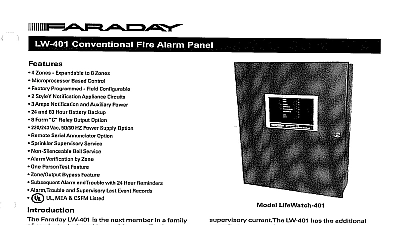
LW 401 Conventional Fire Alarm Panel 4 Zones Expandable to 8 Zones Microprocessor Based Control Factory Programmed Field Configurable 2 Style Y Notification Appliance Circuits 3 Amps Notification and Auxiliary Power 24 and 60 Hour Battery Backup 8 Form Relay Output Option 220 240 Vac 50 60 HZ Power Supply Option Remote Serial Annunciator Option Sprinkler Supervisory Service Non Silenceable Bell Service Alarm Verification by Zone One Person Test Feature Zone Output Bypass Feature Subsequent Alarm and Trouble with 24 Hour Reminders Alarm Trouble and Supervisory Last Event Records MEA CSFM Listed Faraday LW 401 is the next member in a family products designed to provide cost effective life safety equipment to the fire alarm market microprocessor based fire alarm control panel is with four conventional zones and is expand to eight It has many features required by today market such as field programmability limited circuits one person test remote and sufficient power to meet ADA for signaling LW 401 is designed to meet the varied fire alarm of small office buildings apartment buildings stores hotels strip malls or anywhere a efficient general purpose fire alarm control is required and Features Circuits base LW 401 has four conventional Style B zones which any combination of 30 compat smoke detectors can be combined on a zone number of thermal detectors manual stations other compatible direct shorting devices may be to each zone All of these initiating devices be mixed on the same zone providing the total requirement of the zone does not exceed 9 mA LifeWatch 401 current The LW 401 has the additional to support detector accessories such as remote alarm lamps and audible bases zones can be programmed for many func Alarm verification allows detector application sensitive areas with or without manual stations on the zone as allowed by code Manual operation shall not be delayed on verified Generic zone function allows the NAC in the to follow the action of a master fire alarm in the facility zones can also be bypassed as required for during construction on the premises system is expanded through the model expander which has an additional four circuits in addition to relays and open outputs The system can alternately be through the model 16412B expander which has an additional four Class A Style D circuits The 16412B also converts the four circuits and the two notification circuits on main LW 401 to Style D Class A and Style Z A respectively Appliance Circuits base LW 401 has two Style Class B Notifica Appliance Circuits each rated at 1.5 Amps The power output of the panel between the two circuits and the auxiliary output is limited 3 Amps The LW 401 notification circuits are power to reduce installation costs without the of any hardware 3 Amps is sufficient to provide power for applications requiring appliances designed ADA specifications Notification Circuits can be for various codes These include tempo march time simplified zone code and number of They can also be inhibited during test and functions The two circuits can be programmed as non silenceable This operation can be used for strobes which must operation after audible devices are silenced and Outputs base LW 401 has form relays for general and trouble rated at 1 Amp 30 VDC The model optional expander module has an additional general purpose programmable relays rated at 2 30 VDC plus four programmable open outputs the model 16404B relay module pro eight general purpose programmable relays at 2 Amps 30 Vdc 120 Vac All remote opera in the fire alarm system are controlled from the or the 16404B both of which are installed the LW 401 enclosure and Audible Indicators LW 401 has visible LED annunciation by zone alarm and trouble Additionally there is a system LED and a system trouble LED Supervisory utilize the zone trouble LED flashing in sync a system supervisory LED to indicate an off situation with the system alarm trouble and supervi LEDs are also LEDs for AC power bypass and mode A seven segment display reports code for each system trouble and is also used testing and programming functions Trouble are also annunciated by a piezoelectric housed inside the LW 401 annunciation is accomplished through a connection with the model 16409B eight zone annunciators These units display alarm supervi and trouble conditions for 8 zones A total of two can be attached to each system The comes with a black enclosure the with a white enclosure Power LW 401 contains a 1 2 Amp auxiliary power which is used to drive remote devices The power of the panel between the auxiliary output the two notification circuits is 3 Amps Supply Battery Charger power supply accepts a 120 Vac 60 Hz input or a 220 240 Vac 50 Hz input On loss of AC the system switches to battery operation and such by flashing the AC power LED on display Battery capacities of 24 and 60 hours available Controls LW 401 display has four switches for acknowl alarm supervisory and trouble conditions notification appliance circuits resetting the and for the drill function These switches are used when programming the control unit Programmability and Test Functions following functions are field programmable in LW 401 These features are generally not pro in the unit as received from the factory programming is accomplished through the and does not require the use of a computer any proprietary tools Circuits Verification by Zone Zone Bypass Zone or Generic Zone when the is to be used to provide remote appliance circuits The default mode is an alarm causing zone Appliance Circuits Simple Zone Coding March Time Silence Inhibit Cutoff Timers and The default mode is a steady signal Outputs Relays Programming to Output Matrix and Password Maintenance tests features include the One Person Test a Lamp Test and Search and Clear of the trouble and supervisory history buffer and Architect Specifications fire alarm control panel shall be a Faraday LW shall utilize conventional zones shall be micro based and fully field programmable The panel shall include four initiating zones relays general alarm and trouble and two power notification circuits capable of a total of Amps of power and supervisory history notification appli circuit coding alarm trouble 24 hour re and zone output bypass system shall be expandable via a model expander module which shall contain additional four conventional zones four general relays and four general purpose open outputs fire alarm system shall have the following subsequent alarm and trouble one test feature brown out protection 24 or 60 battery backup It shall also have the following features supervisory zones alarm by zone non latching zones alarm initiating device circuit shall have the capabil of being mapped to any optional output via the programming function fire alarm control panel shall be UL listed and the requirements of NFPA 72 for local fire control for automatic or manual service and sprinkler supervisory and waterflow service shall meet NFPA 72 requirements for central service when connected to the model DC or DC 101 digital fire communicator Diagram All field wiring must be in accordance NFPA 70 article 760 Make no wiring connections while the is powered Alarm relay contacts are shown de energized Trouble relay contacts are shown energized Auxiliary output rated 0.5 amps at 24 Vdc maximum line impedance of 5 ohms Combined current output for NAC1 NAC2 and outputs is limited to 3.0 amps Equipment connected to these terminals must located within the same room Refer to the LW 401 Operation Installation and Maintenance for further details No t tapp