Faraday - MPC-1000 Addressable Fire Alarm Control Data Sheet

File Preview
Click below to download for free
Click below to download for free
File Data
| Name | faraday-mpc-1000-addressable-fire-alarm-control-data-sheet-4856913027.pdf |
|---|---|
| Type | |
| Size | 635.33 KB |
| Downloads |
Text Preview
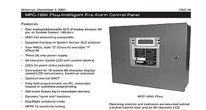
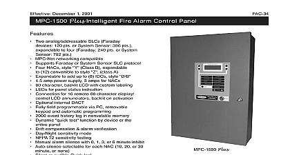
Effective December 1 2000 replaces April 1 2000 Addressable Fire Alarm Control Panel One analog addressable SLC 198 pts Four NACs style Y Class A Three 3 amp power supply 80 character backlit LCD with custom labeling LEDs for panel status indication Connection for 16 remote 80 character display LCD annunciators backlit on activation Optional DACT connection Fully field programmable via PC removable or automatic programming 500 event history log in nonvolatile memory Dynamic quick test functions Day Night sensitivity mode NFPA 72 sensitivity testing Manual alarm silence with 0 1 3 or 6 minute inhibit Auto silence selectable for each NAC 10 20 or 30 or none Test by device or the entire panel Silent or audible Quick Test 59 Software zones 255 notification and 255 relay circuits Two password levels UL Listed standard 864 CSFM listed and MEA Made in U S A ISO 9001 quality crafted MPC 1000 is an advanced modular fire alarm It features analog addressable detection and memory capability It base con includes one analog addressable loop with conventional notification appliance output circuits controls and indicators are mounted behind locked cabinet door and an 80 character LCD provides specific indications for addressable while LEDs indicate general panel status Configuration main termination board mounts in the rear of the The main power supply is physically contiguous the main termination board The MPC 1000 main board provides the interface for external system connections the analog loop interface four signaling circuits remote signaling circuits indicating interfaces and the electronics of the system power supply front main logic PCB mounts in the back box it to carry the controls and displays which are from the front locked panel door Displays any number of zones are handled through this continued 1 Addressable Fire Alarm Control Panel normal operation is controlled from the front of the via push button switches Displays are provided an 80 character alphanumeric backlit LCD display by discrete LED indicators for major panel func p Normal STATUS DISPLAY 01 15 99 80 character LCD display is used to display event including alarms and troubles identification of or device and of The display controlled by a of four push switches the processor back light is in the to assure in low light to conserve it is only during a event or of a control switch SILENCE 1000 SILENCED UNIT BEFORE SERVICING SILENCE CONTROL RESET POWER ON ALARM Control Unit Configuration Addressable Input Output Circuits addressable main termination board has loop interface circuitry supporting addressable device communication loop Notification Appliance Circuits base panel has four independent NACs Each can be selected to give continuous output of eight sounding patterns or zone coding are style Z or Y capable without additional Dry Contacts Three form C dry relay contacts provided These contacts are dedicated to trouble and supervisory indications Digital Dialer Output The main analog board provides a standard DACT providing more extensive data to a receiving station Remote Annunciation The MPC 1000 panel drive up to 16 annunciators and 8 remote on an RS 485 communication line Power Supply A 3.0A 24V nominal power provides all operating power to the panel for standby and alarm conditions 2.5 Amps are for the NAC circuit LCD Annunciator Specifications Temperature F 0 49 cid 176 C Humidity Extreme 85 F Consumption 025 Amp 020 Amp Format supervised limited STATUS DISPLAY Normal p 01 15 99 ON ALARM ENABLE character alphanumeric backlit gang box supplied by others ohms line 4000 ft max pair for data Weight lbs approx 2 Addressable Fire Alarm Control Panel Devices Remote LCD Annunciator RDC 1 The remote annunciator consists of a backlit 80 character display 4 menu buttons 4 dedicated for operator interaction 6 LED indicators a security key switch Serial Annunciator SAU 1 Consists of remote and annunciator driver board capable of 16 supervised outputs for LEDs or lamps Expansion to drive 512 LEDs lamps is via additional processor boards and drive boards Serial Relay Unit SRU 1 Consists of remote and relay board which provides 8 relays form C dry contacts rated at 1 amp to 192 relays is via additional remote boards and relay boards Serial Annunciator Extender Each remote board receives commands from the unit and is capable of controlling three relay and four annunciator boards Maximum of 8 processor boards in one system Auxiliary supplies will be required to power units the control unit capability Main Termination Board All wiring must be accordance with local and National Electric Use only FPL FPLR FPLP as described in 760 of N E C wiring and installation information owner manual 447051 Device Circuit 4 6 or 7 Operation jumper P1 for proper style nominal Resistance 20 ohms line Power Limited Owner Manual for Compatible Devices 6 7 4 60Hz max Supervised Limited Set to 38AH O C O C C O Contacts in normal condition Resistive Power Limited Unsupervised 24V 24V 24V Power 0.5A max 24VDC nominal Limited All Non Power Limited Wiring from Power Limited Wiring Interface Circuit nominal 0.4A max Resistance 25 ohms line 4000 ft max Type Twisted Pair for Data Power Limited X X A B C D shown in activated condition Y Class B Power Limited Z Class A Power Limited Typical above Typical above Ratings Voltage 24VDC nominal Alarm Current 1.5A Ripple 16VAC Wire Voltage Drop 1.0VDC Standby Current 1.0mA The maximum current all NACs is 2.5A 3 Addressable Fire Alarm Control Panel Specifications STATUS DISPLAY Normal p 01 15 99 POWER ON SILENCED SILENCE SILENCE RESET 1000 ALARM CONTROL UNIT BEFORE SERVICING temperature F 0 49 cid 176 C Humidity 86 cid 176 F Supply input voltage Vac 50 60 Hz 240 Vac 50 60 Hz primary input current amp 120 Vac and Trouble Power Supply volt lead acid battery with 7 AH 38 AH Power Outputs 0.5 amp resettable