Faraday - MPC-1500 Plus Fire Alarm Control Panel Data Sheet

File Preview
Click below to download for free
Click below to download for free
File Data
| Name | faraday-mpc-1500-plus-fire-alarm-control-panel-data-sheet-0971486532.pdf |
|---|---|
| Type | |
| Size | 622.71 KB |
| Downloads |
Text Preview
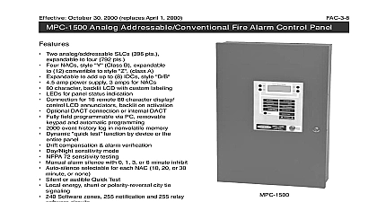
Effective December 1 2001 Plus Intelligent Fire Alarm Control Panel Two analog addressable SLCs Faraday 120 pts or System Sensor 396 pts to four Faraday 240 pts or System 792 pts MPC Net networking compatible Supports Faraday or System Sensor SLC protocol Four NACs style Y Class B expandable 12 convertible to style Z class A Expandable to add up to 8 IDCs style D B 4.5 amp power supply 3 amps for NACs 80 character backlit LCD with custom labeling LEDs for panel status indication Connection for 16 remote 80 character display LCD annunciators backlit on activation Optional internal DACT Fully field programmable via PC removable and automatic programming 2000 event history log in nonvolatile memory Dynamic quick test function by device or the panel Drift compensation alarm verification Day Night sensitivity mode NFPA 72 sensitivity testing Manual alarm silence with 0 1 3 or 6 minute inhibit Auto silence selectable for each NAC 10 20 or 30 or none Silent or audible Quick test Local energy shunt or polarity reversal city tie 240 Software zones 255 notification and 255 relay circuits Coded output Two password levels Tech Maintenance Transient protected UL Listed standard 864 CSFM MEA pending Made in USA ISO 9001 quality crafted MPC 1500 Plus is an advanced modular fire panel It features analog addressable detection and memory capability and is capable of special expansion modules to allow the of up to 8 local conventional style D B zones It base configuration includes two loops with four conventional appliance output circuits controls and indicators are mounted on the with a mylar label for identification An 80 LCD display provides specific indications for Plus devices and conventional expansion while LEDs indicate general panel status Configuration main termination board mounts in the rear of the The main power supply is physically contiguous the main termination board The MPC 1500 Plus termination board provides the interface for analog system connections a platform for the driver board four signaling circuits remote circuits and indicating interfaces and the of the main system power supply Expan termination boards mount in the rear of the control above the main board They provide the inter for an additional loop driver board and conven zone interface boards expanding the capability the panel from two loops unneeded loop capability not be programmed in to four loops and eight input zones in the extended cabinet loop signal expansion board also provides four signaling circuits and each conventional expan termination board provides two more signaling for a system maximum of 12 1 continued Plus Intelligent Fire Alarm Control Panel front main logic PCB mounts on the cover of the allowing it to carry the controls and displays which be accessible from the front panel The system and low level logic are included on this to leave the power handling to the heavier in the back of the box Since displays for any of zones are handled through this board no of this board is required for system normal opera is controlled the front of the via push switches an enabling required all functions display of most recent event are by an 80 alphanu backlit LCD and by LED for major functions STATUS DISPLAY Plus Normal p 01 01 02 POWER ON SILENCED SILENCE SILENCE RESET Plus ALARM CONTROL UNIT BEFORE SERVICING 80 character LCD display is used to display event including alarms and troubles identification of or device and presentation of history The is controlled by a set of four push button commanding the control processor Opera of the key switch is required to call up any but the recent active event A back light is included in the to assure visibility in low light but to conserve it is only activated during a reported event or of a display control switch Control Unit Configuration Addressable Device Circuits addressable main termination board mounts addressable loop interface board supporting two device circuits Supports Faraday or Sensor SLC protocol Notification Appliance Circuits base panel has four independent NACs Each can be selected to give continuous output or of eight sounding patterns or zone coding Dry Contacts Five dry relay contacts are These contacts are dedicated to alarm supervisory AC failure and processor indications City Tie The city tie circuitry is located the main termination PCB Shunt local energy polarity reversal mode may be selected by of a programming header Only one mode only one output may be selected The output be alarm trouble supervisory or trouble Digital Dialer Output The main termination provides a optional DACT DEM 1 interface system event data to a remote receiving Remote Annunciation The MPC 1500 Plus will drive up to 16 annunciators RDC 1 and remote processors SAU 1 SRU 1 on an communication line Power Supply A 4.5A 24V nominal power provides all operating power to the panel for standby and alarm conditions Control Unit Configuration Loop Signal Expansion Board LSE 1 four additional NACs The LDBS option two SLC loops Only one LSE 1 can be used Conventional Expansion Board CEB 1 IDCs may be included in the system adding one or two conventional expansion boards Each board provides 4 initiating which can be converted to class by the addition of a class A adapter board CEB 1 board also includes two notification circuits DACT Expansion Module DEM 1 The DEM 1 a dual line digital alarm communications It parameters are set via the control programming sequence The DEM 1 may be in the main enclosure An extended is required if more than one expansion is to be used DEM 1 is compatible with the following SIA DCS 8 SIA DCS 20 Ademco Contact 3 1 1400 Hz 3 1 2300 Hz 4 2 1400 Hz and 2300 Hz MPC Networking The MPC 1500 Plus is MPC networking compatible 2 Plus Intelligent Fire Alarm Control Panel Devices Remote LCD Annunciator RDC 1 The remote annunciator consists of a backlit 80 character display 4 menu buttons 4 dedicated for operator interaction 6 LED indicators a security key switch Serial Annunciator Unit SAU 1 The remote is used with LED or incandescent modules to perform programmed Main Termination Board Serial Relay Unit SRU 1 Each remote relay contains 8 form C relays Each remote board can then address up to 24 The MPC 1500 panel will control eight for a total of 192 relay addresses RS 232 Isolator Module SIB 1 Converts the printer connection to an isolated output or 240 Supply to TB14 DG O A O A O A C A Tie Trouble rated 2A 30 Vdc 5A Vac resistive MON PWR Trouble Limited 1 2 3 4 ohm rated 1.5A max Power Input connections remote printer connections remote LCD processors connections SLC lo