Fike D 1 08 01 Cybercat 1016 Intelligent Fire Alarm Control System

File Preview
Click below to download for free
Click below to download for free
File Data
| Name | fike-d-1-08-01-cybercat-1016-intelligent-fire-alarm-control-system-5381247906.pdf |
|---|---|
| Type | |
| Size | 1.24 MB |
| Downloads |
Text Preview
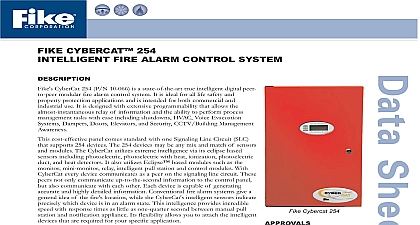
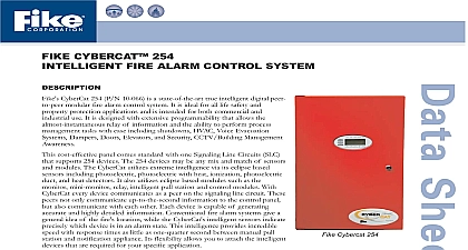
FIKE CYBERCAT 1016 FIRE ALARM CONTROL SYSTEM CyberCat 1016 P N 10 064 is a state of the art true intelligent digital modular fire alarm control system It is ideal for all life safety and protection applications and is intended for both commercial and use It is designed with extensive programmability that allows the relay of information and the ability to perform process tasks with ease including shutdowns HVAC Voice Evacuation Dampers Doors Elevators and Security CCTV Building Management cost effective panel comes standard with two Signaling Line Circuits SLC support 254 devices each This is expandable to four loops and a total panel of 1016 devices with any mix and match of sensors and modules The utilizes extreme intelligence via its eclipse based sensors including photoelectric with heat ionization photoelectric duct and heat It also utilizes Eclipse based modules such as the monitor mini relay intelligent pull station and control modules With CyberCat device communicates as a peer on the signaling line circuit These peers not communicate up to the second information to the control panel but also with each other Each device is capable of generating accurate and detailed information Conventional fire alarm systems give a general idea of fire location while the CyberCat intelligent sensors indicate precisely which is in an alarm state This intelligence provides incredible speed with times as little as one quarter second between manual pull station and appliance It flexibility allows you to attach the intelligent devices are required for your specific application System is programmed with either the Windows based field configuration C LINXTM or through a comprehensive password protected front panel programming option This option allows you to quickly update and adapt any future requirements or changes in the system such as changes in or remodeling The sophisticated control panel circuitry coupled with software allows you to read specific information and sensitivity levels of the Eclipse devices The sensors also compensate for any changes due to contamination or other environmental factors Operation CyberCat Control system operates on a Zone and State relationship In this all input and output devices must be assigned to at least one zone or to all 254 are available each one defining an area to be protected Input devices be assigned up to four zones one zone is typical and output devices may be for up to 254 zones devices use the SLC signaling line circuits to exchange status information other devices as well as with the control panel When an input is activated it configured to cause its associated zone to enter into an operational state Any device will cause the associated zone to enter into an alarm state The devices are configured to activate to protect and evaluate the endangered This system is completely modular allowing you the flexibility to design a that is just right for your application A typical configuration is shown on 2 that illustrates the communications of a CyberCat system CyberCat 1016 UL S2203 FM 3020297 City of Denver CSFM 7165 0900 137 MEA 490 04 E S 10th Street P O Box 610 Blue Springs Missouri 64013 0610 U S A 816 229 3405 816 229 4615 www fike com No D 1.08.01 5 Cont FEATURES SPECIFICATIONS Cybercat features are designed to save lives and protect your valuable capital through unprecedented speed intelligence and flexibility These features Two 24VDC 2A NAC bell circuits on main board with built in System Sensor or synchronization protocol 254 user defined zones 80 character backlit LCD display Real time clock 3200 event history buffer Critical process monitoring One person Walktest capability Disable by circuit or zone Drill function at panel and remote Provides solenoid releasing operation Alarm verification Easy to add remove devices Diagnostic menus Removable terminal blocks for field wiring Local piezo with distinct event tones 10 Status LEDs to easily identify system status Optional point ID DACT Module available Supports up to 31 peripheral devices such as Remote Display LED Graphic and Annunciators 2 FEATURES SPECIFICATIONS Cont 6 amps useable alarm power expandable to 12 Amps 2 A standby expandable to 4 Operation from 120VAC 60 Hz or 240 VAC 50 Hz Two 24V DC 2A continuous auxiliary power outputs Expandable to 5 circuits with One 24VDC 2A resettable auxiliary power output Supports up to 75AH of batteries expandable to 150 AH using SPS Line Circuit Address devices with Infrared IR tool similar to remote control device Two SLC loops expandable to four NFPA style 4 or 6 254 devices per loop system maximum 1016 devices with SLM Supplemental Loop True peer to peer digital protocol for extremely fast and reliable communications Auto address function Automatic day night sensitivity adjustment Automatic holiday sensitivity adjustment Acclimate operation for sensors IR Tool provides ability to read sensitivity levels or perform remote test of device Devices contain multi color LED for quick reference of device status Sensors provide early warning pre alarm detection and can also provide a summing up to eight sensors Circuit Two NAC circuits standard Rated at 24VDC 2.0 Amps maximum Built in synch protocol for System Sensor Gentex and Wheelock devices SYSTEM MODULES Controller P N 10 2472 Controller contains the power supply microprocessor hardware interface and keypad The controller internal power supply provides 2 Amps Standby Current 6 Amps Alarm Current Comes standard with two line circuits SLCs Steel Enclosure 23.6 H x 14.35 W x 4 D Back box dimensions Enclosure is equipped with a 0.50 wide lip to facilitate flush mounting Removable door for ease of installation Two door options available with or without lexan cover on oval opening Available in red or black Dead Front option available ID Dact Digital Alarm Communicator Transmitter Module P N 10 2528 DACT provides interface with Central Station monitoring systems It is with 5 contact zones of connection OR the intelligent serial interface provides point ID information The Contact ID form is the preferred format It provides a four digit account code followed by a three digit code a two digit group number and a three digit contact number all of are used to provide specific point identification This DACT can also provide SIA or 4 2 Pulse reporting format Note 10 2476 is the same as 10 2528 with for external mounting 3 SYSTEM MODULES Cont Power Supply SPS P N 10 2474 P 10 2474 p includes the power supply circuit board and transformer 1 for primary 2 for 240VAC primary This module adds up to 2.0A standby power and 6.0A alarm power 4 A standby 12A alarm total power and standby batteries are supervised Supports charging up to 75Ah additional standby battery Charging may be turned off in configuration if are not required on SPS Dimensions 4 1 2 L x 5 1 2 H x 2 D 0.66 lbs Loop Module SLM P N 10 2473 SLM adds two more SLC loops Loop specifications and wiring for SLM the same as the main controller It interfaces to the main Control Panel four standoffs supplied with the SLM 2 L x 6 1 2 H x 1 D Weight 0.12lbs Relay Module P N 10 2204 CRM4 provides 4 additional independently programmed relays CyberCat Panel supports up to 2 CRM4 modules if either options are not on the main controller board Each relay may be wired across normally or normally closed contacts Dimensions 3 1 2 L x 1 1 2 H x 2 D 0.10 lbs Reverse Polarity Module CRPM P N 10 2254 reverse polarity module provides the ability for UL Remote Station This supervision is typically performed with a direct leased line It interfaces to the main control board using four standoffs with the RPM Dimensions 3 1 2 L x 1 1 2 H x 2 D 0.08 lbs Remote LCD Display P N 10 2321 module provides information about the host CyberCat System in a remote It receives the intelligent data stream from the RS485 output of the