Fike HFC-227EA Engineered Nozzles C 1 08 01

File Preview
Click below to download for free
Click below to download for free
File Data
| Name | fike-hfc-227ea-engineered-nozzles-c-1-08-01-1589463702.pdf |
|---|---|
| Type | |
| Size | 694.74 KB |
| Downloads |
Text Preview
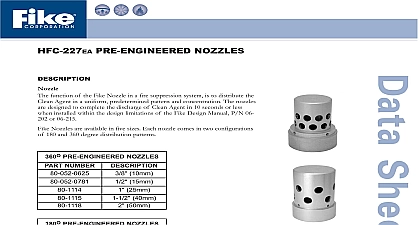
HFC 227EA ENGINEERED NOZZLES function of the Fike Engineered Discharge Nozzle in a fire extinguishing is to distribute the Clean Agent in a uniform predetermined pattern and The nozzles are designed to complete the discharge of Clean in 10 seconds or less when installed within the design limitations of the Design Installation and Maintenance Manual P N 06 202 or 06 215 and the Flow Calculation computer program Engineered Discharge Nozzles are available in sizes of 3 8 10mm 2 50mm Each nozzle is available in 180 and 360 degree discharge Discharge Nozzle size refers to the size of Schedule 40 or 80 steel pipe to it can be connected The nozzle discharge orifices are drilled perpendicular the center line of the threads The nozzles are mounted to allow the agent to discharged on a horizontal axis orifices are available in a wide range of sizes to provide accurate Clean flow results All nozzles have been tested for their ability to discharge the Agent under extreme conditions orifice drilling must be done at the Fike factory or other UL listed nozzle station only after As Built calculations of the installed piping system s been performed using the Fike Flow Calculation computer program Fike Discharge Nozzle used shall be Factory Mutual FM approved and Laboratories UL listed AND ENGINEERING SPECIFICATIONS nozzle used to disperse Clean Agent shall be a Fike Series 80 The nozzle shall be available in 3 8 10mm thru 2 sizes Each size shall be available in both 180 and 360 degree dispersion patterns The nozzle used shall have pipe that correspond to the nozzle size All nozzles shall have an orifice size determined by a UL listed and FM flow calculation program All nozzle orifice drilling shall be performed by the manufacturer or a UL listed nozzle facility Engineered Nozzles UL Listed Ex4623 ULC Listed CEx1136 FM Approved 0Y4A8 AF No C 1.08.01 2 S 10th Street P O Box 610 Blue Springs Missouri 64013 0610 U S A 816 229 3405 816 229 0314 www fike com Size and Area Coverage Nozzle Nozzle Area Coverage Type Degree 8 13.92 Degree 8 9.04 Height to 16.0 to 4.9 to 16.0 to 4.9 SIZE NOZZLE NUMBER NOZZLE NUMBER 1 4 1 2 The maximum allowable area of coverage includes any area within the radius distance from the nozzle R dimension to the most extreme wall or Nozzles should be located on center line of hazard area When working with ceiling heights exceeding the values tabulated above the hazard volume must be broken down into vertically stacked hazard with heights less than the maximums shown in the table is imperative that unusual applications of this nature be handled by experienced design engineers and in most cases operational tests should be before the system is put into service Dimensions and nozzle data shown are taken from the UL listed and FM approved Design Installation Maintenance Manual 180 and 360 degree nozzles may be placed a maximum of 1 foot 30.5cm down from the ceiling and 180 degree nozzles may be placed a 06 202 or 06 215 of 1 foot 30.5cm from the wall Nozzle threading is NPT Fike Corporation All Rights Reserved No C 1.08.01 2 March 2004 Specifications are subject to change without notice