Fike Interface Firing Module C 1 06 01
File Preview
Click below to download for free
Click below to download for free
File Data
| Name | fike-interface-firing-module-c-1-06-01-5142837960.pdf |
|---|---|
| Type | |
| Size | 706.73 KB |
| Downloads |
Text Preview
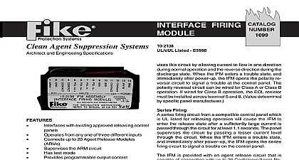
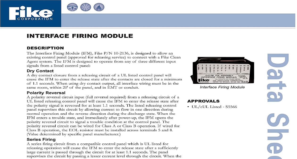
Interface Firing Module UL cUL Listed S5566 FIRING MODULE Interface Firing Module IFM Fike P N 10 2136 is designed to allow an control panel approved for releasing service to connect with a Fike Clean system The IFM is designed to operate from any of three different input from a listed control panel Contact dry contact closure from a releasing circuit of a UL listed control panel will the IFM to enter the release state after the contacts are closed for a minimum 1.1 seconds When using dry contact output all interface wiring must be in the room within 20 of the panel and in EMT or conduit Reversal polarity reversal circuit input full reversal required from a releasing circuit of a listed releasing control panel will cause the IFM to enter the release state after polarity signal is reversed for at least 1.1 seconds The listed releasing control supervises this circuit by allowing current to flow in one direction during operation and the reverse direction during the discharge state When the enters a trouble state and immediately after power up the IFM opens the reversal circuit to signal a trouble condition at the control panel The reversal circuit can be wired for Class A or Class B operation If wired for B operation the EOL resistor must be installed across terminals 5 and 8 determined by specific panel manufacturer Firing series firing circuit from a compatible control panel which is UL listed for operation will cause the IFM to enter the release state after a sufficiently current is passed through the circuit for at least 1.1 seconds The panel the circuit by passing a lesser current level through the circuit When the enters a trouble state and immediately after power up the IFM opens the firing circuit to signal a trouble condition on the control panel IFM is provided with an agent release circuit that is capable of connecting up to 20 Containers Agent Release Modules ARM III Fike P N 10 1832 also supervises the integrity of the ARM circuit via Class B wiring by utilizing a ohm end of line device connected at the ARM activation of any one of the three types of inputs for a period of at least 1.1 the IFM will energize the ARM III module s which in turn fires the to release the agent programmable output contact is a form A dry contact which can be set via switches for NO or NC operation It also can be programmed for activation trouble or system alarm IFM is a power limited device which requires 24VDC input power from the control panel module is designed to electrically isolate the input circuits from the output to provide flexibility IFM is housed in an enclosure 4 x 3 x 1.5 10.2 x 7.6 x 3.8 cm This can be mounted in the control panel or a separate enclosure An optional enclosure 10 x 6 x 2.5 25.4 x 15.2 x 6.4 cm with cover is offered P N wiring shall be with conductors approved for use in this application The IFM a removable terminal strip that can accommodate wiring sizes from 18 to AWG S 10th Street P O Box 610 Blue Springs Missouri 64013 0610 U S A 816 229 3405 816 229 4615 www fike com No C 1.06.01 2 FEATURES SPECIFICATIONS Interfaces with existing approved releasing Series Firing Input Maximum supervision current 3.0 mA Minimum release current 8.0 mA Maximum release voltage 25.5 VDC Minimum release voltage 20.7 VDC Typical input impedance 1.5K ohm Dry Contact Input Maximum Voltage across contact 30 VDC Maximum Current through contact 50 mA Dry Contact Output Rating Maximum voltage 30 VDC Maximum current 1.0 A ARM Circuit rating Maximum Agent Release Modules 20 Operates from any one of three different Connects up to 20 Agent Release Modules panels Supervises the ARM circuit Has test mode Provides programmable output contact Operating Voltage 21 27 VDC Current Normal 45 mA Max Release 70 mA Max Trouble 150 mA Max Polarity Reversal Input Maximum supervision voltage 30 VDC Maximum release voltage 30 VDC Minimum release voltage 12 VDC Minimum release current required 5 mA DIAGRAM III 10 1832 OHM WATT III 10 1832 TO 20 AGENT RELEASE PER CIRCUIT EOL FIRING RELEASE CONTACT INPUT REVERSAL SHOWN IN CONDITION FIRING CIRCUIT CONTACT INPUT 0.2 AMP one of three outputs Listed Control Panel For Releasing Service Monitor Circuit release or trouble VDC Power Fike Corporation All Rights Reserved No C 1.06.01 2 March 2005 Specifications are subject to change without notice