Fike System Sensor Duct Smoke Detector

File Preview
Click below to download for free
Click below to download for free
File Data
| Name | fike-system-sensor-duct-smoke-detector-4920816375.pdf |
|---|---|
| Type | |
| Size | 229.64 KB |
| Downloads |
Text Preview
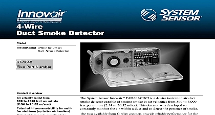
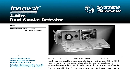
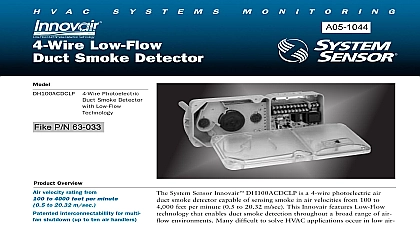
4 Wire Smoke Detector 4 Wire Ionization Smoke Detector Overview velocity rating from to 4000 feet per minute to 20.32 m sec interconnectabillity for multi shutdown up to ten air handlers telescopic sampling tube cover tamper trouble signal VAC DC or 120 240 VAC operation voltage barrier with two DPDT Form C relay reset button mounting tabs and quick mounting to round rectangular ducts from 1 meters wide to clean recognized and sensor boards test station option sounder option cover for convenient inspection 268A listed warranty model available System Sensor Innovair DH100ACDCI is a 4 wire ionization air duct detector capable of sensing smoke in air velocities from 500 to 4,000 per minute 2.54 to 20.32 m sec This detector was developed to monitor the air within a duct and to detect the presence of smoke two available form C relay contacts provide reliable performance for the of fans blowers and air conditioning systems These HVAC can be con to prevent the spread of toxic smoke and gasses a protected area Innovair family is designed for simpli installation and easy mainte The modular construction allows for easy cleaning and uncomplicated replacement of the UL recognized power and sensor boards The patented missing feature insures the cover is securely tightened following routine and maintenance The patented interconnectability feature allows mul Innovairs to communicate with each other In the event smoke is detected Innovair will signal the remaining interconnected detectors to initiate their for smoke control Duct smoke detectors have speci limitations SMOKE DETECTORS ARE a substitute for an open area smoke detector a substitute for early warning detection and a replacement for a building regular system to NFPA 72 and 90A for additional information about the proper of duct smoke detectors Speci air duct smoke detector shall be a System Sensor Model DH100ACDCI Series Duct Smoke Detector The detector shall be UL listed per UL 268A specifically for use in air handling systems The detector shall operate at air veloci of 500 feet per minute to 4000 feet per minute 2.54 to 20.32 meters second The unit shall be capable of control up to ten 10 air handling systems when interconnected with other detectors The detector shall be capable of pro a trouble signal in the event that the front cover is removed It shall be capable of local testing via magnetic switch remote testing using the SSK451 Multi Signaling Accessory or the RTS451KEY Remote Test Station The unit shall be by local reset button or remote test station The duct smoke detector housing shall incorporate an airtight smoke in compliance with UL 268A Standard for Smoke Detectors for Duct Applications The housing shall be capable mounting to either rectangular or round ducts without adapter brackets An integral filter system shall be included to dust and residue effects on detector and housing thereby reducing maintenance and servicing Sampling tubes either be telescoping or be easily installed by passing through the duct housing after the housing is mounted to the The unit shall provide a spacial separation of no less than 1 6.4 mm and or a physical barrier between the high low voltage terminals The enclosure shall meet all applicable NEC and NFPA standards regarding electrical junction Terminal connections shall be of the strip and clamp method suitable for 12 AWG wiring Guide wiring diagram for 4 wire duct smoke detectors INPUTS ACCEPT cid 31 VDC 24 VAC 50 60 HZ cid 31 VAC 50 60 HZ OR cid 31 VAC 50 60 HZ cid 31 POWER SOURCE cid 31 APPROPRIATE TERMINALS cid 31 EACH DETECTOR CONTACT RATINGS cid 31 30 VDC RESISTIVE cid 31 250 VAC cid 31 MINIMUM 5 VDC cid 31 INTENDED FOR cid 31 TO CONTROL cid 31 POWER INPUTS POWER INPUTS AUXILIARY CONTACTS cid 31 FAN SHUTDOWN ETC AUXILIARY CONTACTS cid 31 FAN SHUTDOWN ETC AUXILIARY CONTACTS SHOWN IN cid 31 CONTACTS TRANSFER DURING cid 31 AS INDICATED BY THE ARROWS AUXILIARY CONTACTS SHOWN IN cid 31 CONTACTS TRANSFER DURING cid 31 AS INDICATED BY THE ARROWS CONTACT RATING cid 31 A 30 VDC resistive TROUBLE CONTACTS TROUBLE CONTACTS POWER SOURCE cid 31 APPROPRIATE TERMINALS cid 31 EACH DETECTOR SEE cid 31 FOR cid 31 POWER SUPPLY cid 31 WIRING OF AUXILIARY cid 31 REFER TO cid 31 INSTRUCTIONS cid 31 CONTACT MANUFACTURER THE SUPERVISORY RELAY NOW cid 31 A FORM C CONTACT FOR cid 31 APPLICATIONS cid 31 STANDARD APPLICATIONS ONLY cid 31 NO CONTACT IS USED CONTACTS CLOSED IN ALARM AND STANDBY cid 31 OPEN WHILE DETECTOR PCB OR POWER IS cid 31 OR WHEN TAMPER FEATURE TIMES OUT OPEN cid 31 SIGNAL TROUBLE CONDITION TO PANEL CONTACTS CLOSED IN ALARM AND STANDBY cid 31 OPEN WHILE DETECTOR PCB OR POWER IS cid 31 OR WHEN TAMPER FEATURE TIMES OUT OPEN cid 31 SIGNAL TROUBLE CONDITION TO PANEL SHOWN cid 31 IN STANDBY cid 31 CLOSE cid 31 ALARM SHOWN cid 31 IN STANDBY cid 31 CLOSE cid 31 ALARM LISTED 4 WIRE cid 31 PANEL DETECTOR IN THE LOOP cid 31 DETECTOR IN THE LOOP cid 31 RESISTOR cid 31 BY cid 31 MANUFACTURER 37 cm Length 14 cm Width 7 cm Depth Weight lbs 1.7 kg Temperature Range to 120 F 0 to 49 C Humidity Range to 93 relative humidity non condensing Duct Velocity to 4000 ft min 2.54 to 20.32 m sec Ratings DH100ACDCI Includes Detector supply voltage capacitance voltage time with RTS451 time by power down up time response time Test VDC max VDC min to 0.3 sec sec max sec max to 17 sec VAC 50 60 Hz VAC 50 60 Hz VAC 50 60 Hz max VAC min to 0.3 sec sec max sec max to 17 sec VAC min to 0.3 sec sec max sec max to 17 sec VAC min to 0.3 sec sec max sec max to 17 sec detector label detector label detector label detector label Supply Voltage 29 VDC VAC 50 60 Hz VAC 50 60 Hz VAC 50 60 Hz mA mA mA RMS mA RMS mA RMS mA RMS mA RMS mA RMS REQUIREMENTS USING NO ACCESSORIES standby current alarm current RATINGS initiation contacts SPST 30 VAC DC 0.6 power factor auxiliary contacts DPDT 30 VDC 250 VAC Alarm auxiliary contacts must switch 100mA minimum at 5VDC Alarm auxiliary contacts shall not be to inititaing circuits of control panels Use the alarm initiation contact for this purpose contacts SPDT 30 VDC resistive CURRENT LOADS AT 24 VDC Max Max Max Max Max Max Max Max When a unit is powered at the 120VAC or 220 240VAC input any combination of accessories may be used such that the given accessory loads are mA or less in the standby state 110 mA or less in the alarm state Interconnect Notes When using the interconnect feature all interconnected must be powered with the same independent supply Polarity must be maintained throughout the interconnect Connect terminal 12 on unit 1 to terminal 12 on 2 and so on Similarly connect terminal 1 on unit 1 to 1 on unit 2 and so on diagram