Fike System Sensor i3 Series Photoelectric Smokes A05-0318

File Preview
Click below to download for free
Click below to download for free
File Data
| Name | fike-system-sensor-i3-series-photoelectric-smokes-a05-0318-5472906381.pdf |
|---|---|
| Type | |
| Size | 647.27 KB |
| Downloads |
Text Preview
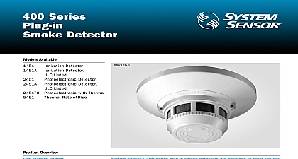
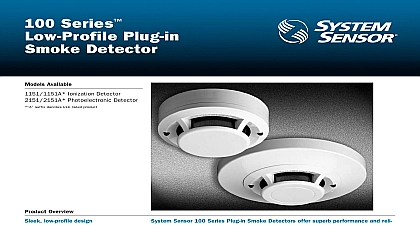
C O N V E N T I O N A L D E T E C T I O N Photoelectric Detectors Available Models Models standard standard with thermal standard standard with thermal loop test maintenance module reader tool adapter bracket Overview detector line mounting base wire entry port terminals with SEMS screws to octagonal and single gang 4 square backboxes or to ceiling Lock attachment to base detector cover and chamber easy cleaning remote maintenance signaling compensation and smoothing sensitivity measurement angle dual color LED indication testing via EZ Walk feature test switch Sensor i3 series smoke detectors represent a signi advancement in detection The i3 family is founded on three principles Installation Intelligence and Instant inspection ease The i3 line rede installation ease with its plug in design allows an installer to pre wire the bases included with the heads The large entry port and in line terminals provide ample room for neatly routing the inside the base The base accommodates a variety of back box mounting as well as direct mounting with drywall anchors To complete the i3 heads plug in to the base with a simple Stop Drop Lock i3 detectors offer a number of intelligent features to simplify and maintenance Drift compensation and smoothing algorithms are with the i3 line to minimize nuisance alarms When connected to the loop test maintenance module or a panel equipped with the i3 2 wire i3 detectors are capable of generating a remote maintenance when they are in need of cleaning This signal is indicated via an LED at the module and the panel To read the sensitivity of i3 detectors the is a wireless device that displays the sensitivity in terms of percent foot obscuration inspection The i3 series provides wide angle red and green LED indica for instant inspection of the detector condition indicating normal standby alarm or freeze trouble conditions When connected to the loop test maintenance module or a panel with the i3 protocol EZ Walk loop test feature is available on 2 wire i3 detectors This feature the initiating loop wiring by providing LED status indication at each Speci detector shall be a System Sensor i3 model number listed to Laboratories UL 268 for Fire Signaling Systems The detector be a photoelectric type model 2W B or a combination photoelectric ther model 2WT B 4WT B with thermal rated at 135 57.2 The detec shall include a mounting base for to 31 and 4 inch octagonal gang and 4 inch square back boxes Specifications Voltage 12 24 V non polarized V V Ripple Voltage peak to peak of applied voltage a plaster ring or direct mount to the using drywall anchors Wiring con shall be made by means of SEMS The detector shall allow pre wiring the base and the head shall be a plug in The detector shall have a nominal of 2.5 per foot nominal as in the UL smoke box The detec shall be capable of automatically adjust its sensitivity by means of drift compen and smoothing algorithms The shall provide dual color LED indi which blinks to indicate power up standby out of sensitivity alarm freeze trouble model 2WT B 4WT B When used in conjunction with 2W MOD2 module 2 wire models include a maintenance signal to indi the need for maintenance at the alarm panel and shall provide a loop test capability to verify the circuit without each detector individually Current 50 maximum average 50 maximum average Alarm Current 130 mA limited by control panel 20 mA 12V 23mA 24V Standby Current 100 n a Contact Ratings n a 0.5 A 30V AC DC Up Sequence for LED Indication LED status indication seconds octagonal back box octagonal back box gang back box square back box with a plaster ring mount to ceiling Modes Mode up standby of sensitivity trouble LED every 10 seconds every 5 seconds LED every 10 seconds every 5 seconds every 10 seconds Specifications Temperature Range and 4W B 32 0 and 4WT B 32 0 Humidity Range to 95 RH non condensing Sensor 57.2 nominal Terminals AWG including base inches 127 mm diameter inches 51 mm height Trouble and 4WT B only 41 5 oz 178 grams Information Wiring Current mA max limited by control panel mA max limited by control panel mA 12V 23mA 24V mA 12V 23mA 24V loop test maintenance module reader replacement tool adapter bracket 6.6 in 16.76 cm diameter Sensor Sales and Service Sensor Headquarters Ohio Avenue Charles IL 60174 800 SENSOR2 630 377 6495 x3 Sensor Canada 905.812.0767 905.812.0771 Sensor Europe 44.1403.276500 44.1403.276501 Sensor in China 86.29.524.6253 86.29.524.6259 Sensor in Singapore 65.6273.2230 65.6273.2610 Sensor Far East 85.22.191.9003 85.22.736.6580 Sensor Australia 613.54.281.142 613.54.281.172 Sensor India 91.124.637.1770 x 2700 91.124.637.3118 2002 System Sensor The company reserves the right to change product speci without notice