DSC AMB 300 IS EN NA

File Preview
Click below to download for free
Click below to download for free
File Data
| Name | dsc-amb-300-is-en-na-3895014276.pdf |
|---|---|
| Type | |
| Size | 716.75 KB |
| Downloads |
Text Preview
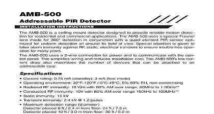
AMB 300 PIR Detector INSTRUCTIONS AMB 300 is a general purpose PIR detector designed to provide reliable motion for residential and commercial applications design care and factory testing ensure years of trouble free performance detectors provide immunity against false alarms from RF static electrical tran and white light signal processing temperature compensation and a large multi beam design means that the human target will not slip by unnoticed on a hot day interchangeable lenses wall or corner mounting and vertical adjustment provide versatility Your client will appreciate the small size and elegant simplicity the case design AMB 300 uses a 2 wire connection for power and to communicate with the con panel This simplifies wiring and reduces installation cost The AMB 300 low cur draw also maximizes the number of devices that can be attached to an loop Current rating 0.75 mA standby 3 mA test mode Operating environment 32 0 5 93 RH non condensing Radiated RF immunity 10 V m with 80 AM over range 80MHz to 1.0GHz Conducted RF immunity 10V with 80 AM over range 150kHz to 100MHz Static immunity 15 kV Transient immunity 2.4 kV 1.2 joules White light immunity 20,000 Lux device Walk detection speed 0.5 10 s 0.15 3m s Coverage angle BV L1 90 minimum Vertical adjustment 5 to 10 Mounting heights 6 10 2 3m nom 7.5 2.3m 4 5 1.2 1.5m pet alley only Tamper switch contact rating 0.1A 24VDC Panel Compatibllity PC4010 4020 v3 x PC5010 PC5015 PC5020 v2 x with interface module Protected by one or more of the following patents 2099971 US 5444432 RF immunity and white light not verified by UL Patterns for Lenses BV L1 to BV L4 the Detector a detector location that will provide the coverage required keeping in mind the potential problems Do not aim the detector at reflective surfaces such as mirrors or windows as this distort the coverage pattern or reflect sunlight directly onto the detector Avoid locations that are subject to direct high air flow such as near an air duct out Do not locate the detector near sources of moisture steam or oil Do not aim the detector such that it will receive direct or reflected mirror sunlight Do not limit the coverage by large obstructions within the detection area such as or filing cabinets When using BV L4 Pet Alley lens Do not aim the detector at a stairway which a pet access to Do not place furniture or objects higher than 3 ft 0.9 m which a pet climb onto e g a cat on a couch closer than 6 ft 1.8 m to the detector Wiring connect the AMB 300 consult the wiring diagram below open the case use a small flat blade screwdriver and gently push in the tab at the of the case and pull the cover straight out at the bottom Loosen the printed board screw and push the board up as far as it will go Using a small screw remove the appropriate knockouts for the mounting screws Remove the wiring entrance knockouts located at the top or bottom of the backplate the backplate mounting screws diagonally opposite each other to prevent the case from Enrollment serial number located on the back of the device must be enrolled into the alarm panel via Installer Programming 8 Installer Code This procedure is for the PC4010 4020 in the control panel Installation Manual and for the panels in the PC5100 Installation Manual Connect only DSC Addressable Series devices to the addressable connections Connection of ANY other type of device will impair operation devices other than Addressable Series devices which require power to oper must be powered separately Adjustment Range and dead zones may vary due to settings the figures listed below set the vertical adjustment to get the desired coverage that the PCB retaining screw is tightened just enough to prevent board movement the circuit board down will increase the far range and bring the near beams closer the mounting wall Moving the circuit board UP will reduce the far range and move the beams farther out from the mounting wall Moving the circuit board UP too much will the far beams to above the target as a result the range may appear shorter J1 selects between harsh and normal environments For a typical environ or one containing a small pet height less than 1.2 ft 0.36 m set the unit as nor J1 ON For a large pet and multiple pets the jumper J1 should be removed Testing the detector has been set up walk test the entire area where coverage is Should the coverage be incomplete readjust or relocate the detector to full coverage NOTE Upon installation the unit should be thoroughly tested to proper operation The end user should be instructed on how to perform tests and should walk test the detector weekly and DM W Detector Mounting Brackets the optional DM W Wall Mount and DM C Ceiling Mount brackets to solve difficult problems The DM W and DM C mount to either the wall or ceiling and for full vertical and horizontal positioning of the motion detector the detector be tilted up or down and rotated through 90 to obtain the best position for opti coverage COMPLIANCE STATEMENT Changes or modifications not expressly approved by Digital Security Controls Ltd could void your to use this equipment equipment generates and uses radio frequency energy and if not installed and used properly in strict accor with the manufacturer instructions may cause interference to radio and television reception It has been type and found to comply with the limits for Class B device in accordance with the specifications in Subpart of 15 of FCC Rules which are designed to provide reasonable protection against such interference in any residen installation However there is no guarantee that interference will not occur in a particular installation If this does cause interference to television or radio reception which can be determined by turning the equip off and on the user is encouraged to try to correct the interference by one or more of the following measures Re orient the receiving antenna Relocate the alarm control with respect to the receiver Move the alarm control away from the receiver Connect the alarm control into a different outlet so that alarm control and receiver are on different circuits necessary the user should consult the dealer or an experienced radio television technician for additional sugges The user may find the following booklet prepared by the FCC helpful to Identify and Resolve Radio Interference Problems This booklet is available from the U S Government Printing Office Washing D C 20402 Stock 004 000 00345 4 WARRANTY Security Controls Ltd warrants that for a period of twelve months from the date of purchase the product be free of defects in materials and workmanship under normal use and that in fulfilment of any breach of such Digital Security Controls Ltd shall at its option repair or replace the defective equipment upon return of equipment to its repair depot This warranty applies only to defects in parts and workmanship and not to damage in shipping or handling or damage due to causes beyond the control of Digital Security Controls Ltd such lightning excessive voltage mechanical shock water damage or damage arising out of abuse alteration or application of the equipment foregoing warranty shall apply only to the original buyer and is and shall be in lieu of any and all other warran whether expressed or implied and of all other obligations or liabilities on the part of Digital Security Controls Digital Security Controls Ltd neither assumes nor authorizes any other person purporting to act on its behalf modify or to change this warranty nor to assume for it any other warranty or liability concerning this product no event shall Digital Security Controls Ltd be liable for any direct indirect or consequential damages loss of profits loss of time or any other losses incurred by the buyer in connection with the purchase installa or operation or failure of this product detectors can only detect motion within the designated areas as shown in their respective installation instruc They cannot discriminate between intruders and intended occupants Motion detectors do not provide volu area protection They have multiple beams of detection and motion c