System Sensor MMF-300 Monitor Module Installation AND MAINTENANCE Instructions
File Preview
Click below to download for free
Click below to download for free
File Data
| Name | system-sensor-mmf-300-monitor-module-installation-and-maintenance-instructions-0137486952.pdf |
|---|---|
| Type | |
| Size | 1.50 MB |
| Downloads |
Text Preview
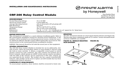
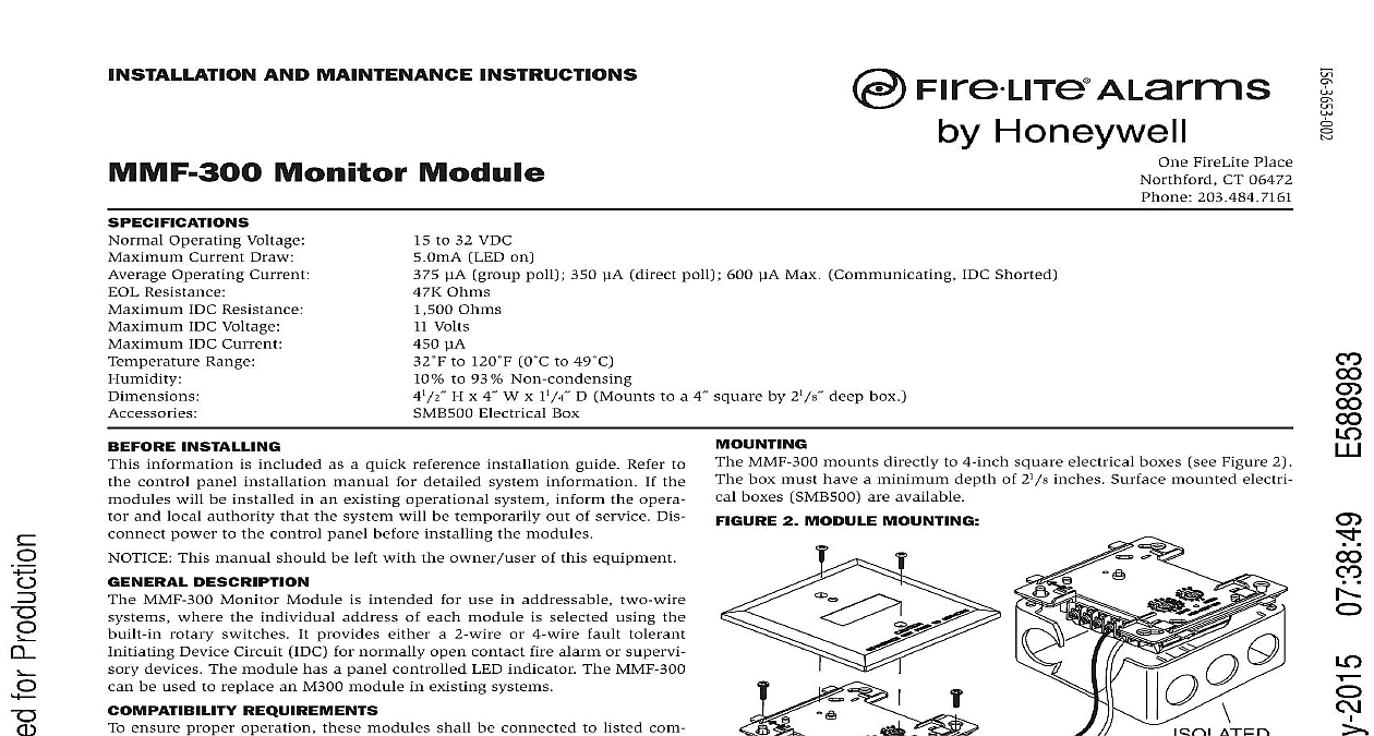
InstallatIon anD maIntenance InstructIons monitor module Operating Voltage Current Draw Operating Current Resistance IDC Resistance IDC Voltage IDC Current Range to 32 VDC LED on group poll 350 direct poll 600 Max Communicating IDC Shorted Ohms Ohms Volts to 120 0 to 49 to 93 Non condensing H x 4 W x 11 4 D Mounts to a 4 square by 21 8 deep box Electrical Box FireLite Place CT 06472 203.484.7161 MMF 300 mounts directly to 4 inch square electrical boxes see Figure 2 box must have a minimum depth of 21 8 inches Surface mounted electri boxes SMB500 are available 2 moDule mountIng InstallIng information is included as a quick reference installation guide Refer to control panel installation manual for detailed system information If the will be installed in an existing operational system inform the opera and local authority that the system will be temporarily out of service Dis power to the control panel before installing the modules This manual should be left with the owner user of this equipment DescrIptIon MMF 300 Monitor Module is intended for use in addressable two wire where the individual address of each module is selected using the rotary switches It provides either a 2 wire or 4 wire fault tolerant Device Circuit IDC for normally open contact fire alarm or supervi devices The module has a panel controlled LED indicator The MMF 300 be used to replace an M300 module in existing systems requIrements ensure proper operation these modules shall be connected to listed com system control panels only 1 controls anD InDIcators All wiring must conform to applicable local codes ordinances and This module is intended for power limited wiring only Install module wiring in accordance with the job drawings and appropri wiring diagrams Set the address on the module per job drawings Secure module to electrical box supplied by installer as shown in 2 3 typIcal 2 WIre InItIatIng DevIce cIrcuIt IDc confIguratIon nfpa style B class B NEXT NUMBER OF UL LISTED CONTACT DEVICES MAY BE USED DO MIX FIRE ALARM INTIATING OR SECURITY DEVICES THE SAME MODULE EOL DEVICE CIRCUIT IDC NFPA STYLE B LIMITED 450 MAX 11 VDC MAX CONTACT CLOSURE DEVICES PER INSTALLATION INSTRUCTIONS WIRING SHOWN IS SUPERVISED AND POWER LIMITED 4 typIcal 4 WIre fault tolerant InItIatIng DevIce cIrcuIt IDc confIguratIon nfpa style D class a OR MODULES TO LISTED CONTROL PANELS ONLY LINE CIRCUIT SLC VDC MAX PAIR RECOMENDED OR MODULES TO LISTED CONTROL PANELS ONLY LINE CIRCUIT SLC VDC MAX PAIR RECOMENDED NEXT NUMBER OF UL LISTED CLOSURE DEVICES BE USED DO NOT MIX FIRE INTIATING SUPERVISORY SECURITY DEVICES ON THE MODULE RESISTOR INTERNAL TERMINALS 9 CONTACT CLOSURE DEVICES PER INSTALLATION INSTRUCTIONS WIRING SHOWN IS SUPERVISED AND POWER LIMITED FireLite Alarms Inc