Hochiki FNV-5022 Rev E EVX-4Z 6-30-09

File Preview
Click below to download for free
Click below to download for free
File Data
| Name | hochiki-fnv-5022-rev-e-evx-4z-6-30-09-6129345078.pdf |
|---|---|
| Type | |
| Size | 671.69 KB |
| Downloads |
Text Preview
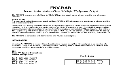
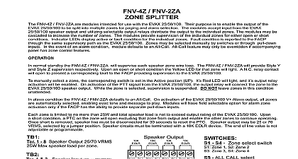
FNV 4Z FNV 2ZA SPLITTER FNV 4Z FNV 2ZA are modules intended for use with the FNV 25 50 100 Their purpose is to enable the output of the EVAX 25 50 100 to be into multiple zones for paging and alarm selection The modules accept input from the FNV 25 50 100 speaker output and utilizing selectable relays distribute the output to the individual zones The modules may be cascaded to increase the number of zones The modules provide of the individual zones for either open or short conditions Indicator LEDs display active or fault condition for the individual zones condition is reported to the FACP through the same supervisory path as the FNV 25 50 100 Zones may be selected manually by switches through pull down inputs In the event of an alarm condition module defaults to an All Call All Call feature may only be overridden if panel has zone control features normal standby the FNV 4Z FNV 2ZA will supervise each speaker zone wire loop The FNV 4Z FNV 2ZA will provide Style Y and Style Z respectively Upon an open or short condition the Yellow LED for that zone will light A N C relay contact will open to present a fault to the FACP providing supervision to the FNV 25 50 100 manually select a zone the corresponding switch is set in the Active position UP It Red LED will light and it output relay activation will be On activation of the PTT signal from the FNV 25 50 100 the output relay will connect the zone to the FNV 25 50 100 speaker output alarm condition the FNV 4Z FNV 2ZA defaults to an All Call On activation of the FNV 25 50 100 V Alarm output all zones are automatically enabling evac tone and message to play Modules will have field selectable option for alarm zone activation only if the FACP has the to provide separate pull down inputs 50 100 is limited to no more than 25W per zone and total speaker load is not to exceed output rating of the FNV 50 100 FNV 25 is limited to more than 10W per zone and total speaker load is not to exceed output rating of the unit Upon a short condition a PTC on the zone will open that zone from output and enable the other zones to continue operating Speaker output may be 25 or 70 Vrms Installer must insure the proper PTC value is used as determined by the Wattage and Voltage setting of the amplifier which is driving the Zone Splitter See PTC below Speaker circuits must be terminated with a 10K EOLR device The end of line value is not adjustable or programmable The FNV FNV 2ZA is jumper selectable for General Alarm enable disable 1 8 Speaker Output 25 70 VRMS Max speaker load per zone Max per zone when used with an EVX 25 1 2 Speaker Input 25 or 70VRMS 3 PTT Push To Talk signal when main system microphone active 4 V 24V DC 0.10A 5 Alarm Active when programmed event active at main Bell secondary message etc 6 Circuit Negative 7 8 9 Aux Trouble Common Relay N O 8 C 9 N C Ratings 1A 30VDC to Resistive Load Class II Power or Power Sources Only Interconnected Equipment be in Same Room and Mounted Within 20 10 11 Supv Circuit Input 1 2 FACP EOLR Supv Out Relay 3 7 Aux Zone Activate Pull Down point to ckt neg for external zone selection 3 ALL CALL 4 Zone 4 5 Zone 3 6 Zone 2 7 Zone 1 Output 8 4 3 2 1 6 5 8 7 S4 Zone select switch Zone 1 S2 Zone 2 Zone 3 S4 Zone 4 ALL CALL select 1 yel Zone 1 Fault 2 red Zone 1 Selected 3 yel Zone 2 Fault 4 red Zone 2 Selected 5 yel Zone 3 Fault 6 red Zone 3 Selected 7 yel Zone 4 Fault 8 red Zone 4 Selected On General Alarm Enabled Off for 4 Zone Class B On for 2 Zone Class A Short circuit protection 1 4 EVX 50 100 025 25V 075 020 70V 025 wiring connections wire clamp screw 14 18 AWG wire clamp screw 12 18 AWG wire entry terminal 18 26 AWG gauge determined by circuit load are provided with the Zone Splitter To proper operation the appropriate PTC be installed to match the amplifier 24 VDC 0.051A Standby 0.130A ALL CALL Active FNV 5022 Rev E 1 of 2 Village Drive Suite 100 Park CA 90621 2268 Technical Support SPLITTER WIRING DIAG 1 2 3 4 B Style Y Wiring wire run to maintain supervision not loop wire around speaker terminals faults are indicated at 10K impedance or less wiring connections wire clamp screw 14 18 AWG wire clamp screw 12 18 AWG wire entry terminal 18 26 AWG gauge determined by circuit load 8 Active Neg 4 3 2 1 6 5 8 7 2 3 SPLITTER UNIT WIRING DIAG Dry Contact Per Zone for By Zone operation and wiring customer supplied A Style Z Wiring 1 2 25 50 100 8 8 EOLR 2 1 4 3 4 3 6 5 6 5 8 7 8 7 2 1 units may be daisy chained in the fashion Insure that EOLRs are installed at Zone Splitter to maintain supervision wiring shown is Power Limited must insure that wiring and devices in the system meet the current National Code NFPA 70 and all applicable state local building code requirements all field wiring use FPL FPLR or FPLP as per NFPA 70 Article 760 wiring connections wire clamp screw 14 18 AWG wire clamp screw 12 18 AWG wire entry terminal 18 26 AWG gauge determined by circuit load FNV 5022 Rev E 2 of 2 Village Drive Suite 100 Park CA 90621 2268 Technical Support