Hochiki FNVOpManualR6A

File Preview
Click below to download for free
Click below to download for free
File Data
| Name | hochiki-fnvopmanualr6a-1789423506.pdf |
|---|---|
| Type | |
| Size | 703.28 KB |
| Downloads |
Text Preview
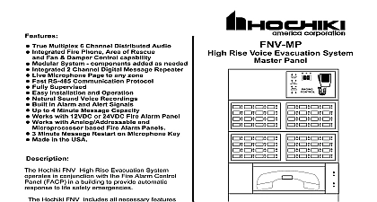
VoiceNET Rise Multiplex System 101.3 Information PRODUCT OVERVIEW Hochiki FNV High Rise Evacuation System operates in conjunction with the Fire Control Panel FACP in a building to provide automatic audio response to life emergencies Hochiki FNV includes all necessary features to provide an effective voice evacuation The Hochiki FNV can be custom configured to satisfy the needs of any high rise department authorities can easily take command of evacuation or relocation and emergencies Building management and fire brigades can monitor and emergency response even before the professionals arrive FNV system includes capacity for 6 channels of simultaneous audio This provides evacuation stay in place or other public address announcements and automatic Features features may include Fire Fighter Phones or Warden Stations as required by code Custom messages and tones may be incorporated into the system technical assistance please contact installing dealer or Technical Assistance Hochiki FNV Multiplex System System Layout Panel Evacuation Circuits Audio Amplifiers Phone Panel Evacuation Circuits CONTROL Audio Amplifiers Phone Loop Twisted Pair Refer to last page for specs and descriptions Panel End Control Panel and Displays Display System Reset All Call Silence Test CONTROL ZONE CONTROL Microphone LEDs LEDs Phone PHONE CONTROL FUNCTIONS Control Panel status indicators are Alarm Fault and Power Power On Diagnostics the system is scanned for active Distributed Panels and The Message Display indicates how many Distributed Panels have been found and event buffers are cleared The green indicator is on as long as there is power available to the FNV Master The red indicator will be on whenever an Alarm condition exists The yellow indicator will be on blinking whenever a fault has occurred in the FNV the fault is active an audible indicator will sound and the Message display will indicate a code the fault that has occurred A list of these Fault codes is on page 9 These Fault conditions are serviceable by the user please contact your installer In addition the audible fault signal will active beep tone as long as the fault persists The Fault Silence switch can be used to the audible fault indication but the visual indicator can only be cleared by an FNV System a single click will clear the flashing LED if the fault condition no longer exists The FACP will indicate a fault as long as an active fault condition exists It may return to normal or remain in depending on the Fire Panels own operational guidelines All Call switch will select all available Evacuation Paging zones on the Paging Zone Control when clicked Individual paging zones may be deselected using the Paging Zone Control but a second click of the All Call switch will deselect the remainder Display Microphone System Reset All Call Silence Test CONTROL FUNCTIONS Zone Control Panel Switch led Status switches are three position and rest at the center position They may be momentarily clicked or down Configured For Speaker Zones and Manual Message Playback solid red Zone selected click switch up to select up again to deselect flashing red Alarm condition reported yellow Fault detected audible tone will also be present solid green Zone selected for message playback click switch down to select down again to deselect Configured For Fire Phone Zones flashing red call in a fireman phone is plugged in at that location Audible ring in tone will be active until Call is acknowledged and connected solid red connected click switch up to connect up again to disconnect yellow fault detected audible tone will also be present Configured for Speaker Zones and Zone Expansion is on is ready for alarm zone expansion System is in Alarm click switch down to select LED will flash red SWITCH PANEL LOCATED ON FNV Master Panel FUNCTIONS Phone Phone Handset When a Fire Phone Handset is plugged into a Fire Phone Jack the LED on Zone Control panel associated with that Fire Phone zone will start flashing A ringing signal will heard to indicate that a handset has been jacked in The ringing signal will cease when that Fire Zone is selected click switch up You may then communicate with the emergency worker picking up the red fire phone handset Phone Zone Normally only one Fire Phone Zone is selected at a time Selecting another where a handset is jacked in will deselect the other zone s Where more than one zone is to selected at a time Party Line mode must be selected Phone Circuit If a fault is detected on any Fire Phone circuit the LED will change to yellow the audible fault tone will be present Control Located on FNV MasterPanel Phone FUNCTIONS Codes Reported On Message Display will flash and then the two letter code every 2.5 seconds Multiple codes will alternate five seconds display in order and then resume at the beginning Display Fault One or more of the system zones is in trouble Associated zone will be flashing Yellow This may be on any Page Phone or Control circuit AC Power Fault Failure Ground Fault Microphone Fault Remote Distributed Panel Fault Will be followed by a designating which panel Interface Fault System communication is compromised Card Fault Switch Interface is in trouble in trouble Note 1 Style 7 FNV Bus Fault Audio Fault Time Out system does not see complete data loop no data on return line 2 the event of any fault condition contact your installing dealer or Technical Assistance 888 382 9835 Display System Reset All Call Silence Test CONTROL Microphone Fault LED will flash when a fault has occurred in the system and the audible trouble will sound The specific fault will be displayed on the MMC and if the fault is with a switch on the SLC Switch LED Card as well the fault is cleared the Fault Message and the audible will reset but the fault Status LED will to flash until the system is reset Fault Messages are displayed one at a time and change every 2.5 Seconds A complete is displayed every 5 Seconds or 7.5 10 Seconds if there are numbers or codes to in the following sequence the fault were a failure in a Remote Panel e g Amp Failure in DP 3 the message would be Description the start of a Fault Message or two character Fault Code numeric code indicates of remote Dist Panel numeric code if number exceeds 99 if the fault were a battery failure the sequence would be until cleared this were accompanied by a microphone fault the sequence would be until cleared repeat until cleared 6 flashing yellow until cleared associated with a given switch such as a Speaker Loop would cause the following message with accompanying switch on the SLC flashing yellow e g an open speaker loop on switch 6 1 The first character of the numeric code displayed left character after the the code is indicates the nature of the Remote Fault If the Remote Panel has stopped responding the will be an asterisk If the Remote Panel is trying to indicate a fault that has no associated or fault code the character will be a plus sign This indicates that there may be a ground fault amplifier module fault or other fault condition in that Remote Panel This must then be investigated at specific panel in fault 2 The specific fault location is displayed on the SLC If the LED for