Honeywell Thermostat PCR-100 User Manual

File Preview
Click below to download for free
Click below to download for free
File Data
| Name | honeywell-thermostat-pcr-100-user-manual-5284673019.pdf |
|---|---|
| Type | |
| Size | 575.95 KB |
| Downloads |
Text Preview
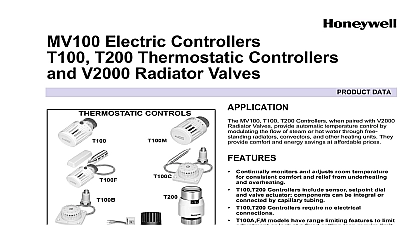
PCR 100 and Operating thermostat OF CONTENTS Unpacking the unit and conditions of use General instructions Use and function Use for the purpose intended Function Safety Sources of danger Safety precautions Installation and commissioning Mechanical installation Electrical installation Operation of the controller Switching on the operating voltage Display Key functions Adjusting the cold store temperature Manual defrost Programming Input parameters and ranges Sensor calibration Parameter E 06 Maintenance Appendix Alarm messages Conditions of warranty Technical data Unpacking the unit and conditions of use and when unpacking the unit make a visual inspection to any possible damage which may have occurred during trans Please look for loose parts dents scratches etc any damage immediately to the freight company Please see if damage has occurred In other instances the latest of the conditions for the supply of goods and issued by the ZVEI German Central Association for the Industry shall apply disposing of the packaging please check it for loose functional and information leaflets that we can process warranty claims please give an exact of the defect with a photograph if appropriate and state model designation of the unit keep these operating instructions at the place where the is used General instructions on the electrical devices and switching equipment may only be out by appropriately qualified personnel The relevant safety environmental regulations must be followed equipment is free from PCBs PCTs asbestos formaldehyde and water repelling substances design of the equipment has taken into account the Standards 50081 1,2 emitted interference EN 50082 1 immunity to inter EN 60335 1 electrical safety IEC 695 2 1 to 2 3 resistance glow wire test tests have been performed in the factory on all equipment in with EN 60335 1 DIN VDE 0700 T500 Use and function Use for the purpose intended controller is designed to control ambient temperatures or temperatures in refrigeration or heating systems controller must not be used as a safety cut out device or excess limiter the unit is used for purposes other than those stated here shall not be considered to be use for the purpose intended Only connect sensors supplied with the unit If a replacement is required only use sensors of the same type No H61007 controller is not intended for use in vehicles because the possi operating voltage ranges interference level and environmental exceed the limits for which the controller can be used take the application limits into account Technical Data in section 11 Function and PCR 110 are general purpose thermostats each with relay output and wide temperature control range to 50 controllers have different housings Modular housing for 35 mm standard rails installation housing which fits into aperture x 70.5 mm Control performance 2 step on off with reversible direction for and refrigerating Defrost option for chilling systems if continuous operation of the fan is foreseen in the switching box to operate thanks to digital input of setpoint value and difference Data is not lost even if there is a power failure for at least years Alarm output Safety Sources of danger Caution Mains voltage Never expose the unit to water or moisture Risk of malfunction short circuit Only use the unit when it is adjusted to normal temperature 15 to 30 Extreme changes in tempe in combination with high atmospheric humidity may lead to formation of condensed water if the control circuit is switched off high voltage may still be to the controller For this reason isolate all electric before starting any service work Never expose the unit to excessive heat dust and vibrations Avoid and pressure loads If the housing is damaged there is a risk an electric shock causing death or injury the unit cannot be operated without the risk of danger it must taken out of service and precautions taken so that it cannot be on again unintentionally applies in particular if the housing has damage which is visible the unit is no longer operational or it has been stored for a long time in unfavourable conditions unit must not be opened If it is thought that the unit may be send it back to the dealer or manufacturer with a precise of the fault Safety precautions All electromagnetic loads solenoid valves contactors horns should be interference suppressed directly at the coil with elements note the maximum contact rating of the relays and this is not observed there is a risk that the contacts may pit or with the result that the refrigeration system will not operate and the refrigerated items may be damaged leads are to be routed separately from mains voltage wires clearance should be at least 5 cm leads must not be routed in multiple cables with other leads mains voltage otherwise the system may malfunction the terminals carefully excessive strain will result in to the controller Installation and commissioning Mechanical installation 4 DIN Standard modular housings to be mounted on a rail housing with 2 mounting tabs out the side mounting tabs clip the unit on to the 35 mm rail press tabs in again housings with 1 mounting tab housing on the upper 35 mm rail Clip the unit on the 35 mm lower tab clips on the rail automatically remove the unit from the rail press in lower mounting tab a driver lift unit Snap in housings the unit in an aperture 28,5 x 70,5 mm and secure it with the mounting frame housings with terminal box coverplate wall thickness 22 mm housings without terminal box cover plate wall thickness 18 mm walls thicker than 10 mm remove lateral plastic spacers from mounting frame For the final fixing of the unit the side screws to be tightened carefully Use a cable clamp to secure sensor T1 in a suitable position Electrical installation CAUTION The mains voltage and system frequency must be the as the nominal values on the device rating plate on electrical systems must be performed by qualified Relevant local safety regulations must be observed diagram Instructions PCR 110 the total current via terminal 5 of the common relay must not exceed 10 A attention to the contact loading of the relay 8A 5A resistive 2A 1A inductive load As a general rule contactors are maximum tested sensor cable length is 50 m with a minimum section of 2 x 0.75 mm2 Solder the extension cable to the cable to prevent contact resistances is advisable to use shielded sensor extension cables All shields be routed at the side of the controller to one earth protec potential The extension cable shield must not be connected on sensor side otherwise bonding currents may occur via the controllers are designed respecting the highest degree of to interference If the local interference level exceeds the data might get lost AL1 in display and the controllers to the preprogrammed setting values This is not a of the controller In such cases the means to suppress have to be improved RC elements shielded lines Operation of the controller view of controller Switching on the operating voltage controller is started by means of a control switch provided by the first time the controller is started pre programmed setting values used which at a later point can be adapted for individual require alarm 2 temperature in refrigerated chamber too high too low is displayed when the controller is switched on this be cleared by pressing the Display normal operation the current cold store temperature is It is measured with cold store sensor T1 the event of an alarm the most recent alarm message e g AL1 the cold store temperature are displayed alternately spot indicators show the switching status of the relays during 1 On Start up dela