Honeywell Thermostat T104F User Manual
File Preview
Click below to download for free
Click below to download for free
File Data
| Name | honeywell-thermostat-t104f-user-manual-9143865027.pdf |
|---|---|
| Type | |
| Size | 874.96 KB |
| Downloads |
Text Preview
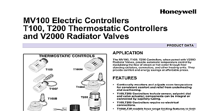
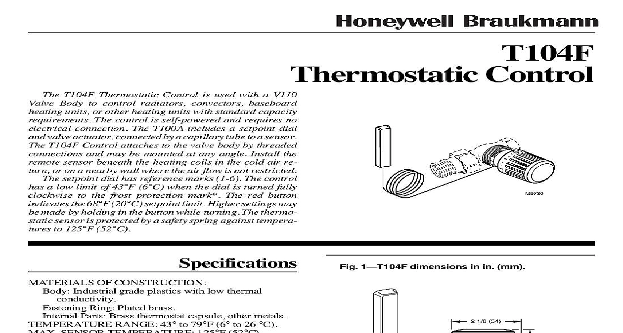
T104F Thermostatic Control T104F Thermostatic Control is used with a V110 Body to control radiators convectors baseboard units or other heating units with standard capacity The control is self powered and requires no connection The T100A includes a setpoint dial valve actuator connected by a capillary tube to a sensor T104F Control attaches to the valve body by threaded and may be mounted at any angle Install the sensor beneath the heating coils in the cold air re or on a nearby wall where the air flow is not restricted setpoint dial has reference marks 1 6 The control a low limit of 43 cid 176 F 6 cid 176 C when the dial is turned fully to the frost protection mark The red button the 68 cid 176 F 20 cid 176 C setpoint limit Higher settings may made by holding in the button while turning The thermo sensor is protected by a safety spring against tempera to 125 cid 176 F 52 cid 176 C OF CONSTRUCTION Industrial grade plastics with low thermal Ring Plated brass Parts Brass thermostat capsule other metals RANGE 43 cid 176 to 79 cid 176 F 6 cid 176 to 26 cid 176 C SENSOR TEMPERATURE 125 cid 176 F 52 cid 176 C OVERALL DIMENSIONS 2 1 8 in 54 mm wide in 84 mm long See Fig 1 LENGTH 6 ft 8 in 2 m SETTINGS are the setpoint temperatures which correspond the setpoint dial reference marks under ideal conditions affecting the temperature at the sensor vary for each It may be necessary to adjust the setpoint or lower to obtain the desired space temperature 43 46 54 61 68 73 79 16 20 23 26 1 8 54 5 16 VALVE BODIES Fig 2 1 dimensions in in mm H 12 94 Inc 1994 Form Number 62 3047 AVAILABLE T100 THERMOSTATIC See Fig 3 Control with internal sensor Control with remote sensor setpoint Control with remote sensor and remote setpoint Control with internal sensor and tamper resistant and mounting Limit Pins Bulb guard for protection of sensor when on the wall 2 Valve Bodies BODIES 3 Thermostatic Controls 4 4 The T104F can be mounted inside an enclo if the sensor is located a minimum of 3 in 76 mm the heating coils in the cold air return Coil capillary tubing beneath and away from the coils Take care not to break kink or sharply the capillary tubing mounting the T104F make sure the bosses on T104F base fit securely into the valve body grooves hand tighten the knurled ring Improper mount can cause overheating Refer to Fig 4 for typical 4 installations INCH the Limit follows set a limit different from the factory setting proceed Determine the desired temperature range limit or lock temperature Select the appropriate number on the ad knob to match the desired temperature setting See 5 and Calibration T104F Control includes an adjustable range limit pin order additional pins separately The pin is fac to limit the low range of the control to the frost setting see Fig 5 The pin can be moved to different low or high limit setting and lock point or it can removed Use a second pin if both low and high limit are desired 5 settings RANGE SETTING MARKING PIN REQUIRED SETTING 79 26 79 26 79 26 68 20 73 23 68 20 73 23 SLOT 2 PIN REMOVED Lift the end cap off the adjustment knob See Fig 6 6 the end cap off the adjustment knob Remove the adjustment knob from the actuator as cid 176 F 22 cid 176 C Turn the adjustment knob so the desired knob setting aligned with the white line on the actuator base Pull the knob off the head or use a screwdriver inserted one of the slots to pry off the knob See Fig 7 7 the knob from the actuator Push the limit pin up and slide it into the slot that LINE HEAD CLIP 3 with the desired temperature limit If the lower remains at the frost protection mark insert an pin in the slot that corresponds with the second 1 the desired temperature range is 43 cid 176 to 73 cid 176 F 6 cid 176 to leave the pin in the slot marked and add one pin in 5 2 the desired temperature range is OFF to 68 cid 176 F 23 cid 176 C the pin to slot 5 No additional pin is required To replace the adjustment knob realign the knob in step 3a with the white line on the base and push the toward the base Make sure the three arm clips snap into at the top of the adjustment knob If the actuator was with the adjustment knob off recalibrate the control to the instructions in Recalibrate T104F Control Replace the end cap the Control at a Single Temperature Determine the desired locking temperature Select the number on the adjustment knob to match the temperature setting See Fig 5 Lift the end cap off the adjustment knob See Fig 6 Remove the adjustment knob from the actuator as Turn the adjustment knob so the desired knob setting aligned with the white line on the actuator base Pull the knob off the head or use a screwdriver inserted one of the slots to pry off the knob See Fig 7 Insert the pin in slot 4a for 68 cid 176 F 20 cid 176 C or slot 4b for 8 the pin in the slot to set the limit PIN LINE STOP FIG 5 To replace the adjustment knob align the knob setting step 3a with the white line on the base and push the toward the base Make sure the three arm clips snap in at the top of the adjustment knob Replace the end cap T104F Control Lift the end cap off the adjustment knob See Fig 6 Pull the knob off the head or use a screwdriver inserted one of the slots to pry off the knob See Fig 7 Turn the actuator head clockwise until the head stops 7 The calibration indent should be aligned approxi with the white line on the base when the head stops the indent is 180 degrees from the white mark unscrew the completely from the base and rethread the head to the so that it is aligned with the white mark Turn the act head clockwise until the head stops Complete removal the head from the base is required only if the actuator was dismantled The distance between the actuator head and the static of the control should be approximately 3 8 in 9 mm Turn the actuator head counterclockwise approxi one turn until the calibration indent on the head aligns the white line on the base For the 72 cid 176 F 22 cid 176 C single setting align the indent with the center of the limiting pin Replace the adjustment knob by aligning the red with the white line on the base and pushing the knob the base For the 72 cid 176 F 22 cid 176 C single temperature align the red button with the center of the adjustable pin Make sure the three arm clips snap in place at top of the adjustment knob Replace the end cap sections of radiator are heating Cause Many radiators are over sized and all are not required to heat up to the set room temperature System is operating properly Sensor is in the wrong location Change the sensor location or change the control See installation instructions Excess capillary tube is coiled above or Coil excess capillary tube below or away from the near the heat source source Flow through the valve is in the wrong Check t