Honeywell Thermostat TR70 User Manual
File Preview
Click below to download for free
Click below to download for free
File Data
| Name | honeywell-thermostat-tr70-user-manual-1368295047.pdf |
|---|---|
| Type | |
| Size | 4.16 MB |
| Downloads |
Text Preview
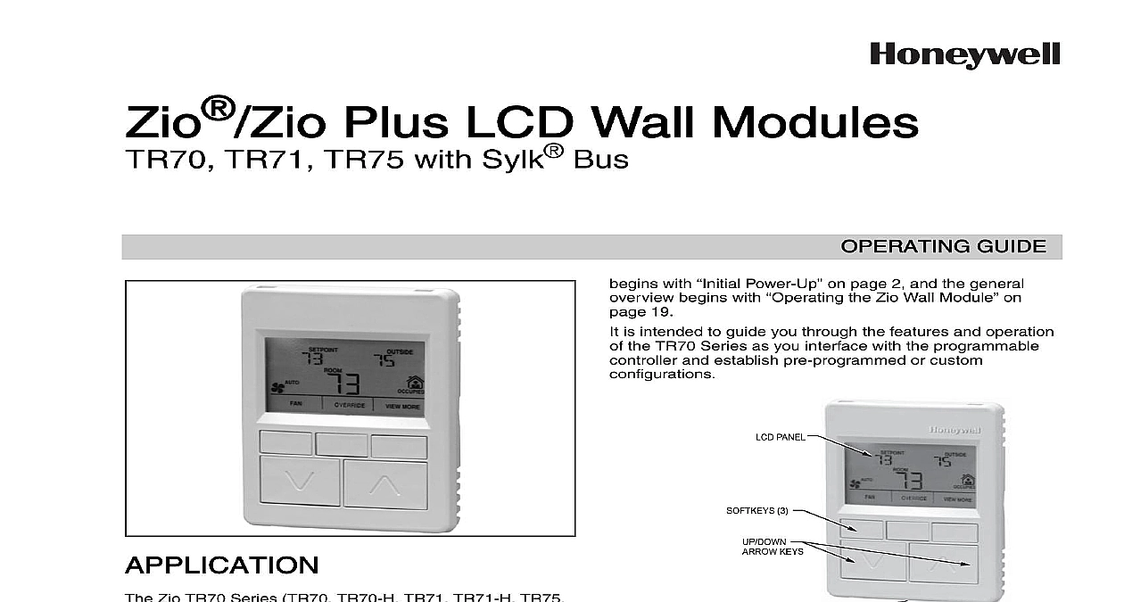
Zio Plus LCD Wall Modules TR71 TR75 with Sylk Bus GUIDE with Power Up on page 2 and the general begins with the Zio Wall Module on 19 is intended to guide you through the features and operation the TR70 Series as you interface with the programmable and establish pre programmed or custom PANEL 3 KEYS BUS PORT ON BOTTOM OF CASE 1 LCD Wall Module features Series Features Power Up and Configuration Setup and Configuration the Wall Module Labels and Memory Usage Module Configuration Settings and Parameters Screen Options and Override 10 Command 12 Status and Command 13 14 15 16 the Setup and Configuration 17 the Zio Wall Module 19 Mode Operation 19 Mode Operation 22 Zio TR70 Series TR70 TR70 H TR71 TR71 H TR75 TR75 H OS numbers LCD Wall Modules provide an interface for monitoring and adjusting parameters in wall module itself and in the programmable controller to the Honeywell Spyder User Guide form 63 2662 the ComfortPoint Programmable Controller User Guide 63 2663 depending on the programmable controller to which it is wired The wall module may be customized supports both a contractor and a tenant user interface This document illustrates the wall module configura process using information from the Honeywell User Guide form 63 2662 wall module has a snap in mounting to a subbase that be mounted on a wall on a standard utility conduit box or a 60 mm wall outlet box Wiring connections to the wall are made through a cutout in the back of the wall models have a space temperature sensor network bus and an LCD panel with three softkeys and two Up Down keys Models with H also include an onboard sensor Operating Guide is intended to provide configuration using the Niagara Workbench tool and a general of the TR70 Series operator interface Configuration PLUS LCD WALL MODULES SERIES FEATURES 1 TR70 Series Features Plus POWER UP Memory bytes to four Zios on Sylk Values Limits as NVs linking possible and Fan command as NVs protection version model visible on and 5 value increments and characters in parameter A maximum of four Zios may be wired on a single Sylk bus no more than one TR70 per bus TR70 Series LCD Wall Modules operate with the Sylk Spyder Controller or the Sylk Enhanced Controller The table below provides information for each model The TR71 TR75 can a TR70 in an installation where an upgrade to WEBs or Spyder or reprogramming is not desired Features like additional memory etc will not be available a TR71 can be replaced by another TR71 or TR75 reprogramming required A TR75 can only be with a TR75 where no reprogramming is desired sure the TR70 Series wall module is properly and properly wired and connected to the controller to the Zio LCD Wall Modules TR70 Series Sylk Bus Installation Instructions form 62 for specific installation requirements initial power up before configuring the wall module the screen displays the phrase LOAd in the Label area of Fig 2 This phrase alternates with any onboard display such as temperature The TR71 TR75 also the firmware revision number model number and Sylk address as shown in Fig 27 2 illustrates all the possible LCD Wall Module display Only those elements pertinent to the current and status actually display CHAR 2 TR70 Series Wall Module LCD screen TR70 TR71 TR75 can be done scenario 2 Compatibility Tool 5.18 Latest 5.18 Old TR71 75 functionality if TR70 is present only TR70 with TR70 functionality can be used but TR70 functionality will there does not recognize the Spyder with TR70 functionality can be used but TR70 functionality will there firmware can be upgraded this becomes scenario Tool can be upgraded this becomes scenario 1 firmware can be downgraded this becomes 4 Spyder firmware and Tool can be upgraded this scenario 1 Tool can be upgraded this becomes scenario 2 firmware can be upgraded this becomes scenario The new Spyder tool 6.0 or greater assumes the latest Spyder capability At download the Tool reads the brand model of the Spyder and determines if it matches the features on the wire sheet If old or new Spyder is programmed with aTR70 can be physically replaced with a TR71 or TR75 AND CONFIGURATION Setup and Configuration the wall module is wired to the controller you configure wall module using the PC based Niagara Workbench Refer to the applicable programmable controller User Refer to the Honeywell Spyder User Guide form 63 or the ComfortPoint Programmable Controller User form 63 2663 depending on the programmable used This tool is used to configure the wall module either the Spyder or the ComfortPoint programmable Bus Address Setting to ensure that the Wall Module bus address dial on the back of the module is set to match the setting the configuration tool TR70 models can be set from 1 TR71 TR75 can be set from 1 0 on the Zio address is equal to 10 in the configuration tool The address must different for each device on the Sylk bus Up to four Zios Spyder are allowed with any combination of TR71 TR75s up to three Zios are allowed if one or more is a TR70 the Wall Module will use the Sylk S Bus wall module function block from Palette Built In folder see Fig 3 This configuration has programmed except the room temperature parameter occupancy status Add the Sylk S Bus Wall Module function block to the sheet via a left click drag and drop See callout 1 Fig 3 Right click on the S Bus Wall Module function block to the Configuration Properties menu See callout 2 Fig 3 Left click on the title Configuration Properties This starts the Configuration Wizard The Configura Wizard steps see Fig 5 on page 4 are used to the wall module CLICK 3 Niagara Tool Interface S Bus wall module selection PLUS LCD WALL MODULES Labels TR71 TR75 allows the use of the following special in label fields such as Categories and Parameter underscore to insert a space hyphen and slash The TR