Kidde 3101033-EN R04 F-Series PCB Replacement Kit Installation Sheet

File Preview
Click below to download for free
Click below to download for free
File Data
| Name | kidde-3101033-en-r04-f-series-pcb-replacement-kit-installation-sheet-5946873210.pdf |
|---|---|
| Type | |
| Size | 1.20 MB |
| Downloads |
Text Preview
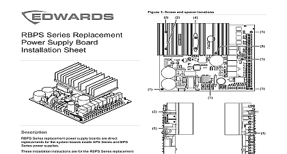
PCB Replacement Kit Sheet replace the PCB Disconnect all field wiring from the PCB each wire so you can identify where to connect them later Remove the dialer if installed Remove the PCB See Figure 1 Do not discard the screws and the replacement PCB using the screws and washers from previous step the dialer and then connect the field wires to the PCB Program the control panel PCB Replacement Kit is used to repair F Series fire alarm control in the field This document provides installation instructions for following models printed circuit board for F Series five zone panels English overlay French overlay printed circuit board for F Series ten zone panels English overlay French overlay replacement printed circuit board PCB is shipped with factory settings If you have changed the default settings you must the panel The dialer if installed doesn require programming instructions refer to the technical manual referenced the label marked Protected Premises Control Unit to the inside of the cabinet door Electrocution Hazard High voltages capable of causing injury including death may be present Disconnect all sources power then wait at least 30 seconds for capacitors to discharge to a energy level before proceeding 2016 United Technologies Corporation 2 3101033 EN REV 04 ISS 31AUG16 1 PCB replacement x 0.375 pan head screw internal tooth washer information contact information see www edwardsfiresafety com 2 3101033 EN REV 04 ISS 31AUG16