Mircom I56-3312 MIX-1251AP (English)

File Preview
Click below to download for free
Click below to download for free
File Data
| Name | mircom-i56-3312-mix-1251ap-english-5483021769.pdf |
|---|---|
| Type | |
| Size | 872.25 KB |
| Downloads |
Text Preview
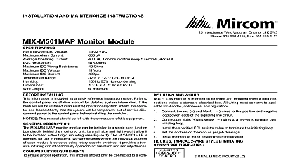
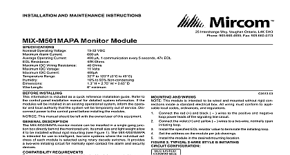
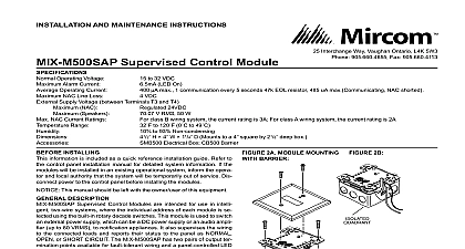
INSTALLATION AND MAINTENANCE INSTRUCTIONS Plug in Intelligent Sensor with Communications Voltage Range Operating Current Alarm Current LED on Humidity Range Temperature Range to 32 VDC 24 VDC one communication every 5 seconds with LED blink enabled mA 24 VDC to 93 Relative Humidity Non condensing to 120 0 to 49 51 mm installed in B210LP Base 155 mm installed in B210LP Base 4.1 104 mm installed in B501 Base oz 153 g Interchange Way Vaughan Ontario L4K 5W3 905.660.4655 Fax 905.660.4113 INSTALLINg sensor must be installed in compliance with the control panel system manual The installation must meet the requirements of the Au Having Jurisdiction AHJ Sensors offer maximum performance when in compliance with the National Fire Protection Association NFPA NFPA 72 DESCRIPTION MIX 1251AP intelligent ionization sensor uses a state of the art sens chamber These sensors are designed to provide open area protection are intended for use with compatible control panels only LEDs on each sensor light to provide a local visible sensor indication LED annunciator capability is also available as an optional accessory MIX 1251AP requires compatible addressable communications to properly Connect this sensor to listed compatible control pan only recommends spacing sensors in compliance with NFPA 72 In low flow applications with smooth ceilings space sensors 30 feet apart For information regarding sensor spacing placement and special appli refer to NFPA 72 or the System Smoke Detector Application Guide from Mircom gUIDE wiring must be installed in compliance with the National Electrical Code local codes and any special requirements of the Authority Hav Jurisdiction Proper wire gauges should be used The installation wires be color coded to limit wiring mistakes and ease system troubleshoot Improper connections will prevent a system from responding properly in event of a fire power from the communication line before installing sensors Wire the sensor base supplied separately per the wiring diagram see 1 Set the desired address on the sensor address switches see Figure 2 Install the sensor into the sensor base Push the sensor into the base turning it clockwise to secure it in place After all sensors have been installed apply power to the control unit and the communication line Test the sensor s as described in the TESTING section of this manual covers provide limited protection against airborne dust particles dur shipping Dust covers must be removed before the sensors can sense Remove sensors prior to heavy remodeling or construction 1 WIRINg DIAgRAM DO NOT LOOP WIRE TERMINAL 1 OR 2 WIRE RUN TO PROVIDE OF CONNECTIONS A OPTIONAL WIRING 2 ROTARy DECADE ADDRESS SWITChES 0 0 MIX 1251AP includes a tamper resistant capability that prevents their from the bracket without the use of a tool Refer to the base manual details on making use of this capability testing notify the proper authorities that the system is undergoing and will temporarily be out of service Disable the system to unwanted alarms sensors must be tested after installation and periodically thereafter Test methods must satisfy the Authority Having Jurisdiction AHJ Sensors maximum performance when tested and maintained in compliance with 72 the sensors as follows functional Magnet Test P N M02 04 01 or M02 09 00 This sensor can be functionally tested with a test magnet The test mag electronically simulates smoke in the sensing chamber testing the electronics and connections to the control panel Hold the test magnet in the magnet test area as shown in Figure 3 The sensor should alarm the panel Two LEDs on the sensor are controlled by the panel to indicate sen status Coded signals transmitted from the panel can cause the to blink latch on or latch off Refer to the control panel technical for sensor LED status operation and expected delay to Smoke Entry Aerosol generator gemini 501 The GEMINI model 501 aerosol generator can be used for smoke entry Set the generator to represent 4 ft to 5 ft obscuration as de in the GEMINI 501 manual Using the bowl shaped applicator aerosol until the panel alarms Additionally canned aerosol simu smoke canned smoke agent may be used for smoke entry testing the smoke detector Tested and approved aerosol smoke product is Smoke Detector Tester model 25S available from Home Safeguard When used properly the canned smoke agent will cause the detector to go into alarm Refer to the manufacturer published for proper use of the canned smoke agent aerosol simulated smoke canned smoke agent formulas will vary manufacturer Misuse or overuse of these products may have long term effects on the smoke detector Consult the canned smoke agent published instructions for any further warnings or caution sensor that fails any of these tests should be cleaned as described under and retested If the sensor fails after cleaning it must be re testing is complete restore the system to the normal operation and the proper authorities that the system is back in operation 3 TEST MAgNET POSITIONINg TEST MAGNET cleaning notify the proper authorities that the system is undergoing and will be temporarily out of service Disable the system to unwanted alarms Remove the sensor to be cleaned from the system Remove the sensor cover Press firmly on each of the four removal tabs hold the cover in place Vacuum the outside of the screen carefully If further cleaning is required with Step 4 otherwise skip to Step 5 Use clean compressed air to remove dust and debris from the sensing Replace the cover using the LEDs to align the cover and then gently it until it locks into place Reinstall the detector Test the detector as described in TESTING Reconnect disabled circuits Notify the proper authorities that the system is back on line NOTE REgARDINg SMOkE DETECTOR gUARDS detectors are not to be used with detector guards unless the combina has been evaluated and found suitable for that purpose 4 SCREEN STATUS TEST MAGNET refer to insert for the Limitations of Fire Alarm Systems STATEMENT device complies with part 15 of the FCC Rules Operation is subject to the following two conditions 1 This device may not cause harmful interference and 2 this device accept any interference received including interference that may cause undesired operation This equipment has been tested and found to comply with the limits for a Class B digital device pursuant to Part 15 of the FCC Rules These limits are designed to provide protection against harmful interference in a residential installation This equipment generates uses and can radiate radio frequency energy and if not installed and in accordance with the instructions may cause harmful interference to radio communications However there is no guarantee that interference will not occur in a particular If this equipment does cause harmful interference to radio or television reception which can be determined by turning the equipment off and on the user is encouraged try to correct the interference by one or more of the following measures Reorient or relocate the receiving antenna Increase the separation between the equipment and receiver Connect the equipment into an outlet on a circuit different from that to which the receiver is connected Consult the dealer or an experienced radio TV technician for help Mircom