Notifier AFP-400 EPROM Installation

File Preview
Click below to download for free
Click below to download for free
File Data
| Name | notifier-afp-400-eprom-installation-3740581926.pdf |
|---|---|
| Type | |
| Size | 1.15 MB |
| Downloads |
Text Preview
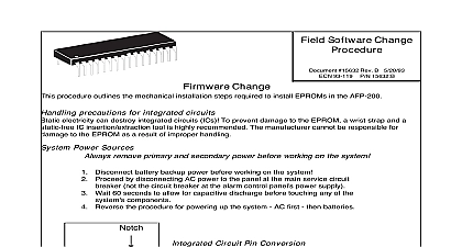
AFP 400 EPROM Installation 50464 Rev B Number 50464 B 96 060 8 22 96 Precautions ICs and Power on Installing an Circuit IC Clintonville Road Northford CT 06472 document contains installation instructions for installing a new EPROM into the Before installation read the electrical precautions and the notes on installing an circuit Integrated Circuits electricity can destroy integrated circuits The manufacturer is not responsible for to an EPROM resulting from improper handling To prevent EPROM damage an IC using the following equipment a grounding pad and wrist strap and a static free IC insertion extraction tool Connections remove primary and secondary power before working on the system Before on the system do the following Disconnect battery backup power Disconnect AC power to the control panel at the main service circuit breaker cid 151 not the breaker at the alarm control panel power supply at least 60 seconds for capacitive discharge before touching any system compo to install an EPROM in the correct orientation will destroy the EPROM the orientation of the EPROM the location of pin 1 in relation to the notch on the on the board shown in Figure 1 Always install a replacement EPROM in the same as the existing EPROM 1 on an IC must seat into position 1 of the socket on the board Most ICs have a or a dot that shows the location of pin cid 160 1 socket for U16 1 1 Locating Pin 1 on the EPROM U16 on the next page the EPROM U16 is located in the lower left area of the CPU 400 board see Figure 2 Before an EPROM note the orientation of the IC look for pin 1 and the orientation of the To replace the EPROM complete the following steps Action all power to the CP 400 board and disconnect optional modules EPROM U16 on the CPU 400 board see Figure 2 below loosen and remove cid 151 preferrably using an extraction tool cid 151 the old EPROM U16 the CPU 400 board the new EPROM a Position the EPROM with the notch facing up and pin 1 lined to pin 1 in the socket then b carefully ease all EPROM pins into the socket cid 151 making not to bend or break any pins cid 151 until all EPROM pins are seated into the socket power to the CPU and connect optional modules 2 shows the location of the EPROM socket on the CPU 400 board and the EPROM in the position for installation socket for U16 Board 1 of detail and Test AFP 400 finished installing the EPROM and connecting power and optional modules reprogram the Test AFP 400 operation to verify proper installation of the EPROM 2 Installing the EPROM U16 on the CPU 400 Board U16