Notifier AM2020-AFP1010 Operating Instructions

File Preview
Click below to download for free
Click below to download for free
File Data
| Name | notifier-am2020-afp1010-operating-instructions-4193526780.pdf |
|---|---|
| Type | |
| Size | 1.01 MB |
| Downloads |
Text Preview
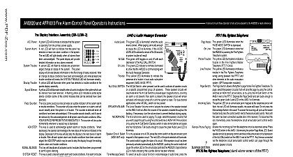
Instr Combination Fire Security Protective Signaling System Operator Instructions Local Ser Displa Power A green LED will illuminate to indicate that the system is Annunciator from the primary power supply Alarm A red LED will flash to indicate that the panel has de at least one fire alarm condition in the system The LED will light steadily when all fire alarms have been The panel display will provide detailed in on any alarms received A yellow LED will flash to indicate any unacknowledged of status in the system The panel display will detailed information about each change of status received After all change of status conditions have acknowledged and while at least one trouble condi still exists the Trouble Security Alarm LED will illumi steadily NOTE Security alarms are considered conditions in this combination fire alarm security system Trouble A yellow LED will illuminate when a trouble condition is detected in the display assembly When this LED is illuminated all information should be considered invalid Silence A yellow LED will illuminate steadily when all the control modules in the system which can be silenced have been silenced A yellow LED indicates a partial signal silence condition some of the control modules that can be silenced have been and A Sounder The local panel piezo sounder provides an audible indication of the system alarm or trouble conditions The sounder will pulse indicate the detection of at least one fire alarm condition in the system and will sound steadily when the system is in trouble sounder is silenced when all conditions have been acknowledged If the sounder sounds steadily and it cannot be silenced the acknowledgment of all system alarm trouble conditions CALL YOUR SERVICE REPRESENTATIVE IMMEDIATELY contact the f This Key is used to acknowledge system alarm or trouble conditions When depressed the operator acknowledges the new of the device indicated on the display Depression of this key will also step the display to the next device in alarm or trouble all such system alarm and trouble conditions have been acknowledged the ACK STEP key may be used to step the display the existing system alarm and trouble conditions SILENCE This key during a fire alarm condition will deactivate all activated control modules that have been programmed to permit signal RESET This key is used to clear all system alarm and trouble conditions If an alarm or trouble condition still exists after System Reset TEST This key is used to automatically perform a test of all intelligent detectors in the system Results of the system detector test are alarm trouble condition will resound indicated on the panel display TEST This key is used to perform a test of LEDs on the control panel and to test the panel display The test will illuminate the panel in sequence for a timed period and flash the panel display When the test has been completed the panel LEDs and the display will return to their prior states Trouble This yellow LED illuminates to indicate a trouble in the system Line This green LED flickers to show that the annunciator is communicating with the control panel The Local Silence Acknowledge Key lights all the LEDs on the ACM 16AT and acknowledges all changes for both the annunciator and the expanders Flashing LEDs on the annunciator will of troub on solid and the piezo sounder will be silenced Note On and expander AEM 16AT or AEM this key serves as a Lamp Test only Control LEDs The red LED associated withe each pint will flash or will illuminate steadily to indicate activation of that alarm or energizing The yellow LED associated with each annunciator point will flash or illumi steadily to indicate a trouble condition on that point ACM 16AT or AEM 16AT only circuits Each key serves to Acknowledge its respective point Pressing the control key after the of a trouble condition will cause the flashing yellow trouble LED to illuminate steadily circuits The control key does not serve as an Acknowledge for this point Pressing the control toggles the state of the output circuit if the circuit is ON pressing the key turns the circuit OFF and versa Zones The control key serves as an Acknowledge for the software zone only and mount these Oper Generator A Level This green LED is illuminated when the audio level is correct only Call This green LED toggles on and off with each depression of the All Call Switch Line This green LED indicator is normally illuminated to show that the control panel is commu This yellow LED illuminates to indicate the presence of a trouble in local audio subsystem with the Audio Message Generator AMG AA 30 FFT 7 only CALL SWITCH The All Call Switch when pressed is used to activate all speaker circuits These speaker will deactivate when the All Call Switch is pressed again toggle function provided alarm is not present If an alarm is present the speaker circuit will remain activated until turned off or until the system is reset For dual channel applications either All Switch can be pushed with the same result VOLUME The Local Speaker Volume control adjusts the volume of the speaker located on the AMG It will not affect the of the speakers installed throughout the building If necessary turn the volume down to prevent feedback paging Circuit Select The microphone is used for paging To page select the speaker circuit s that you wish to page through by using the control keys ACM 16AT Annunciators or by using the All Call Switch Depress the switch on the side of the microphone and speak into the Talk loudly enough to cause the green Audio Level LED to illuminate If the Audio Level LED is allowed to remain off 30 seconds system trouble will result turn a speaker circuit ON press the control key on the annunciator point mapped to that speaker circuit The red LED on the selected will illuminate The control key toggles the state of its circuit If the speaker circuit has been previously activated by the control panel pushing the control key will cause the yellow LED on the annunciator point and the AM2020 Silence LED to flash indicating that a partial silence has been effected Select To select an audio output function voice message or audio tone press the control key on the annunciator Note An active function may have to be deactivated before selection of the next function Select To select a channel press the control key on the annunciator point mapped to the desired channel The red LED on that point illuminate The control key toggles the selection of the channel Channels must be selected for each speaker zone in a dual system Fire Fighter A only ATG 2 provides user selected tones for single or dual channel output When acti the ATG 2 generates either a slow whoop Hi Lo or steady tone on the primary channel In dual channel operation the ATG 2 also generates either chime or a 20 tone on the secondary ALERT channel Line This green LED indicator is normally illuminated to show that the AM2020 AFP1010 is with the Audio Tone Generator Channel This green LED illuminates to show that manual paging will occur over the EVAC channel Channel This green LED illuminates to show that manual paging will occur over the ALERT chan SELECT SWITCH The Page Select Switch when pressed is used to choose between EVAC and ALERT channels for paging The respective LED This yellow LED illuminates to indicate the presence of a trouble in local audio subsystem equipment ATG AA 30 FFT 7 11 04 97 ECN 93 382 P N 15337 C2 The microphone is used for paging To page select the desired channel by pressing the Page Select Switch until the respective illuminate when the channel has been selected FFT Circuit Select only illuminates Depress switch on the side of the microphone and speak into the microphone turn a speaker circuit ON pres the control key on the annunciator point mapped to that speaker circuit The red LED on the will illuminate The control key toggles the state of its circuit If the speaker circuit has been previously activated automati by the control panel pushing the control key will cause the yellow LED on the annunciator point and the AM2020 AFP1010 Silence LED to flash indicating that a partial silence has been effected C r CALL SWITCH To turn on all speaker circuits press the All Call Switch provided separately only Mode FFT green LED illuminates when the Page Switch is depressed