Notifier B610LP Installation Instructions

File Preview
Click below to download for free
Click below to download for free
File Data
| Name | notifier-b610lp-installation-instructions-1953872640.pdf |
|---|---|
| Type | |
| Size | 962.26 KB |
| Downloads |
Text Preview
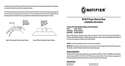
B610LP PLUG IN DETECTOR BASE INSTRUCTIONS USE WITH THE FOLLOWING SMOKE DETECTOR MODELS US EUROPE CP 651E SD 651E SD 651 installing detectors please thoroughly read manual I56 407 Guide for Proper Use of System Smoke Detectors provides detailed information on detector spacing placement zoning wiring and special applications Copies of manual are available from Notifier or a Notifier distributor This manual should be left with the owner user of this equipment The detector used with this base must be tested and maintained regularly following NFPA 72 requirements detector used with this base should be cleaned at least once a year DESCRIPTION Model B610LP detector base is designed for use with Notifier model SD 651 and SD 651E photoelectronic detector and CP 651 and CP 651E ionization detector heads This two wire base is equipped with screw terminals for the of power ground and an optional remote annunciator RATINGS includes base and detector Diameter Height Temperature Range Humidity Range Voltage Ripple Voltage Capacitance Ratings Ratings Voltage Time Time inches 155 mm inches 24 mm lb 137 g square box with or without plaster ring Min depth inches octagon box Min depth inches to 49 32 to 120 to 93 Relative Humidity Noncondensing VDC Volts peak to peak Maximum VDC Minimum VDC Maximum Maximum VDC Minimum at 10 mA VDC Maximum at 100 mA current must be limited to 100 mA by the control panel it is used the RA400Z Remote Annunciator operates within the detector alarm currents VDC Minimum Seconds Minimum Seconds Maximum refer to insert for the Limitations of Fire Alarm Systems 4 I56 646 02R Notifier 1 I56 646 02R 12 Clintonville Rd Northfield CT 06472 1652 203 484 7161 detector base mounts directly to 3 1 2 inch and octagon boxes and 4 inch square boxes with without plaster rings To mount the base remove decorative ring by rotating it in either direction to the snaps before separating the ring from the Use the screws supplied with the junction box attach the base to the box through the appropriate in the base Figure 1 Position the decorative ring around base and rotate it in either direction until the ring into place GUIDELINES loop resistance is an important specification control panels as well as for smoke detectors and bases The alarm system cannot be expected operate correctly if system components have in allowable loop resistances Therefore beginning installation refer to the control panel loop resistance specification to ensure it is listed as compatible with the Notifier base and detector being installed wiring must be installed in compliance with the Electrical Code and all applicable local codes any special requirements of the authority hav jurisdiction using the proper wire size The con used to connect smoke detectors to control and accessory devices should be color coded reduce the likelihood of wiring errors Improper can prevent a system from responding in the event of a fire ON NOT NOT 1 Mounting Base to Box signal wiring the wiring between interconnected detectors it is recommended that the wire be no smaller than AWG However the screws and clamping plate in the base can accommodate wire sizes up to AWG 12 The use of twisted wiring for the power and loop is recommended to minimize the effects of electrical interference To ensure that electrical connections are supervised do NOT loop wires under terminals 2 3 and 5 break the at each terminal make electrical connections strip approximately 3 8 1 cm insulation from the end of each wire Slide the wires under clamp plate and tighten the terminal screw the zone wiring before installing the smoke detector head The built in shorting spring makes it convenient to do IF A REMOTE ANNUNCIATOR NOT USED POLARITY OF TERMINALS MAY BE A OPTIONAL WIRING 2 Wiring Diagram for a Typical 2 Wire Detector System After the detector base is wired and attached to the electrical box position the shorting spring against terminal 3 the slot in the retaining clip to hold the spring against the terminal as shown in Figure 1 This shorts the negative in negative out leads so that loop wiring can be tested for continuity shorting spring in the base will disengage automatically when the detector head is removed from the base DO NOT the shorting spring since it reengages as the detector head is turned into the base completing the circuit FEATURE DO NOT use the tamper resistance feature if the XR2 Removal Tool will be used to remove detectors from the detector base can be made tamper resistant so that the detector cannot be detached without the use of a tool To the base tamper resistant break off the smaller tab at the scribed line on the tamper resistant tab located on the mounting bracket see Figure 3A before installing the detector remove the detector from the base after it has been made tamper resistant remove the decorative ring by rotating it in direction and pulling it away from the base Then insert a small screwdriver into the notch as indicated in Figure and press the plastic lever toward the mounting surface before rotating the detector counterclockwise for removal LEVER TAB AT LINE BY TOWARD OF BASE SMALL BLADED TO PLASTIC LEVER DIRECTION OF LEVER TAB AT LINE BY TOWARD OF BASE SMALL BLADED TO PLASTIC LEVER DIRECTION OF A78 1175 03 3A Activating Tamper resistance Feature 3B Removing Detector Head from Base 2 I56 646 02R 3 I56 646 02R